RADWAG PUE C32 User Manual
Hide thumbs
Also See for PUE C32:
- User manual (106 pages) ,
- Quick start manual (13 pages) ,
- User manual (29 pages)
Table of Contents
Advertisement
Quick Links
Download this manual
See also:
User Manual
Advertisement
Table of Contents

Related Manuals for RADWAG PUE C32


Summary of Contents for RADWAG PUE C32
-
Page 1: User Manual
PUE C32 WEIGHING INDICATOR USER MANUAL ITKU-97-07-10-17-EN www.radwag.pl... - Page 2 OCTOBER 2017...
-
Page 3: Table Of Contents
CONTENTS 1. INTENDED USE............................. 6 2. PRECAUTIONS ............................. 6 2.1. Operation ..............................6 2.2. Battery Power Supply..........................6 3. MAINTENANCE ACTIVITIES ........................7 3.1. Cleaning ABS Components........................7 3.2. Cleaning Stainless Steel Components..................... 7 4. WARRANTY CONDITIONS ........................... 8 5. DESIGN ................................. 8 5.1. - Page 4 15.1.3. Printout Template for Weighing ....................34 15.1.4. Continuous Transmission ......................34 15.1.5. Printout Interval ........................34 15.2. Printer ..............................34 15.2.1. Printer Port ..........................35 15.2.2. Code Page ..........................35 15.2.3. Prefix, Suffix ..........................36 15.2.4. Record of Measurement Data Onto a USB Flash Drive ............36 15.3.
- Page 5 24.3.1. Readout............................ 62 24.3.2. Proximity Sensors........................62 24.3.3. Save Mode ..........................63 24.3.4. Auto Threshold ......................... 63 24.3.5. Result Control........................... 64 24.3.6. Autotare............................ 64 25. WORKING MODE – WEIGHING........................ 65 25.1. Home Screen ............................65 25.2. Local Settings............................65 26. WORKING MODE – PARTS COUNTING ....................65 26.1.
-
Page 6: Intended Use
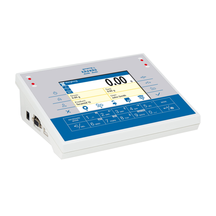
1. INTENDED USE PUE C32 weighing indicator is a device intended to design industrial scales operating on the basis of load cells. The indicator features ABS plastic housing and 5'' colour graphic display ensuring perfect readability. It is operated using 22-key membrane keypad equipped with programmable function keys. -
Page 7: Maintenance Activities
A worn out battery can be replaced only by the manufacturer or by the authorized service. The equipment including accumulators does not belong to regular household waste. The European legislation requires electric and electronic equipment to be collected and disposed separately from other communal waste with the aim of being recycled. -
Page 8: Warranty Conditions
4. WARRANTY CONDITIONS A. RADWAG feels obliged to repair or exchange all elements that appear to be faulty by production or by construction. B. Defining defects of unclear origin and means of their elimination can only be realized with assistance of manufacturer and user representatives. -
Page 9: Connectors Arrangement
Pin8 - TxD2 Pin9 - 5VDC Pin10 - GND Pin13 - RxD2 5.4. I / O Standard PUE C32 indicator is equipped with 4 semiconductor optoinsulated inputs and 4 semiconductor optoinsulated outputs (semiconductor relays). The signals are fed through connector. DSUB15/F... -
Page 10: Technical Specifications
I/O, RS232 DSUB15/F (female) connector, front: Pin1 – GNDWE Pin2 - OUT1 Pin3 - OUT2 Pin4 – COMM Pin6 - IN4 Pin7 - IN3 Pin11 - IN2 Pin12 - IN1 Pin14 - OUT4 Pin15 - OUT3 5.4.1. Technical Specifications Inputs parameters Inputs quantity Inputs type Solid-state relay... -
Page 11: Unpacking And Installation
6. UNPACKING AND INSTALLATION A. Take the indicator out of the packaging. B. Connect the indicator to a weighing platform, next place the weighing device on a flat and even surface. Keep it far away from any sources of heat. 7. -
Page 12: Operation Panel
• pictogram displayed continuously: battery charged within 25% - 50% range of permissible voltage. • pictogram displayed continuously: battery discharged (charge status below 25% of the permissible voltage), connect the balance/scale to the mains in order to charge it. • blinking pictogram: damaged battery or battery lack. -
Page 13: Home Screen
Press to zero the balance/scale. Press to tare the balance/scale. Press to change the weighing unit. Press to confirm the message. Press to confirm the weighing result (PRINT). Press to confirm the messages (ENTER). Press to cancel the messages. Press to change the working mode. Programmable key assigned to a screen button. -
Page 14: Top Bar
9.1. Top Bar The top bar displays the following information: Working mode name and symbol. Weighing device name. Symbol informing that wireless communication is on. Symbol informing that communication with a USB flash drive is on. Symbol informing that PC keyboard is connected. Symbol informing that printer is connected. -
Page 15: Operating The Menu
You can define screen pictograms individually for each working mode. For detailed procedure informing you how to define screen pictograms read section 'Display'. 10. OPERATING THE MENU In order to navigate the program menu use the operation panel. 10.1. Entering the Menu In order to enter the menu press key of the operation panel. -
Page 16: Entering Numeric And Text Characters And Signs
Press to move one menu level up. Press to delete a character when editing numeric and text values . Press to change keyboard mode when editing numeric and text values. Press to select/change working mode. Press to confirm/accept modifications. Press to move one menu level up, or to discard entering parameter modifications. - Page 17 Where: Digits mode. To change keyboard working mode press key. Keyboard working mode options: - digits mode, - arrow keys operation, - bottom line operation. Press to clear box content. Keys: Press to enter digit 1. Press to enter digit 2. Press to enter digit 3.
-
Page 18: Text Box
10.3.2. Text Box Where: Capital letters mode. To change keyboard working mode press key. Keyboard working mode options: - upper-case characters mode, lower-case characters mode, - digits mode, - arrow keys operation, - bottom line operation. Press to save project to *.lb file on USB flash drive. Press to read project saved to *.lb file on USB flash drive. -
Page 19: Diacritical Signs Table
Keys: Press to enter . , { } : ° - . Press to enter a b c. Press to move the cursor to the left, hold the key for a few seconds. Press to enter d e f. Press to move the cursor up, hold the key for a few seconds. -
Page 20: Special Signs Table
Diacritical signs table: English, German, French, Diacritical signs table: Polish. Spanish. Where: Press to activate „Caps Lock” function. !$& Press to switch to special signs keyboard. 10.3.4. Special Signs Table In order to activate special signs table while editing text box it is necessary to press and hold key. -
Page 21: Program
11. PROGRAM Program menu is divided into function groups. Function group is a group of interrelated parameters. Function Groups: • Working modes, • Databases, • Reports, • Communication, • Peripherals, • Printouts, • Display, • Permissions, • Units, • Inputs / Outputs, •... -
Page 22: Log Out Procedure
12.2. Log out Procedure • Go to home screen, press key, wait for the operators database to open. • Select <Log out> option, the home screen is displayed. 12.3. Permissions Levels There are 4 permissions levels: Administrator, Advanced Operator, Operator, None. -
Page 23: Good Weighing Practice
13.1. Good Weighing Practice In order to assure a long-term device operation, wherein correct measurements are provided, the following principles must be adhered to: Avoid applying mechanical shocks to the weighing pan. Place the loads centrally on the weighing pan (refer to section 3.6.2 PN-EN 45501 standard... -
Page 24: Taring Operation
Caution: Indication can be zeroed only within ±2% range of maximum capacity. If the zeroed value is greater than ±2% of the maximum capacity, then the software displays a respective error message: 13.3. Taring Operation To determine net weight value, load the weighing pan with a packaging, wait for a stable indication and press key. -
Page 25: Weighing Unit Change
In case of dual range balances and scales: • Upon switching to weighing with the accuracy of the I weighing range, pictogram/marker is displayed on the left. • Upon switching to weighing with the accuracy of the II weighing range, pictogram/marker is displayed on the left. -
Page 26: Setting Min, Max Thresholds
13.6. Setting MIN, MAX Thresholds MIN, MAX thresholds are used: • to control mass of the weighed loads (read section 24.3.5 of this user manual), • for graphic visualization informing you how much of the weighing device capacity is used (read section 18.1.3 of this user manual), •... -
Page 27: Setting Min, Max Threshold Using Proximity Sensor
13.6.3. Setting MIN, MAX Threshold Using Proximity Sensor • Enter <Working modes> menu and select respective working mode. • Edit a given proximity sensor (left or right). • Select <Set MIN and MAX> parameter from the list. • Exit to home screen. •... -
Page 28: Ethernet
14.2. Ethernet • Select <Ethernet> port. • Set transmission parameters: DHCP Yes, IP Address 0.0.0.0 Subnet mask 0.0.0.0 Default gateway 0.0.0.0 MAC address Caution: 1. Set the transmission parameters in accordance with your local network. 2. <MAC address> parameter is automatically assigned to the weighing device with <Read-only>... -
Page 29: Usb A Port
(e.g. password). Check the settings and try to establish communication again. • If you fail to establish the communication, contact RADWAG service team. The selected network and parameters for connection are stored by the balance/scale program. -
Page 30: Usb B Port
COM port in a computer. To carry out this procedure, you need a respective driver installer which may be either downloaded from www.radwag.pl website or taken from a CD with manuals: RADWAG USB DRIVER x.x.x.exe. Steps: 1. - Page 31 Select directory press „Next” button. In order to start installation process, press „Next” button. Connect the balance/scale to a computer, use 1.8-meter long USB A/B cable maximum (in case already connected balance/scale, it is necessary to disconnect it and reconnect using USB cable).
- Page 32 Press „Finish” button. Connect the balance/scale to a computer again, use 1.8-meter long USB A/B cable maximum. Respective message displayed, press OK button for confirmation. Respective message box is displayed, press OK button for confirmation. „COM ports Screen” automatically displays number of installed COM port.
-
Page 33: Peripheral Devices
15. PERIPHERAL DEVICES 15.1. Computer The weighing device can cooperate with a computer. Active weighing device – computer connection is signalled by pictogram (top bar of the home screen). To configure balance-computer cooperation settings go to < Peripherals / Computer> submenu. 15.1.1. -
Page 34: Printout Template For Weighing
15.1.3. Printout Template for Weighing Template of an individual printout designed using balance/scale and sent to a computer. Procedure: • Enter <Peripherals / Computer / Weighing printout template> submenu, <Weighing printout template> edit box is displayed. • Modify the template and press key to confirm changes. -
Page 35: Printer Port
RS232 port (DSUB15/F connector) for connecting a printer. USB A USB type A port for connecting a PCL or EPSON printer. USB type B port for connecting a computer with RADWAG- USB B designed program, e.g. PW-WIN. Ethernet port for connecting a computer with RADWAG- Ethernet designed program, e.g. -
Page 36: Prefix, Suffix
Exemplary weighing device settings for correct printout of Polish signs with use of EPSON printer connected to RS232 port: EPSON TM-U220D EPSON TM-T20 EPSON TM-T20 Baud rate 9600 bit/s 38400 bit/s 38400 bit/s Parity None None None Code page 1250 Prefix 1B742D 1B7412... -
Page 37: Barcode Scanner
The data may be printed using any printer connected to a computer. New data can be recorded to an existing file therefore it is possible to continue recording measurement data using the file once created. Caution: USB flash drive must comprise <FAT files system>. 15.3. -
Page 38: Prefix, Suffix
Caution: In RADWAG-adopted standard, the prefix is 01 sign (byte) hexadecimal format, the suffix is 0D sign (byte) hexadecimal format. For detailed description of ‘balance’ – ‘barcode scanner’ communication read APPENDIX 01 of this user manual. -
Page 39: Test
Customer Name, Code. Packaging Name, Code. Lot number Batch number *) - <Filtering> submenu hidden. Function inactive. *) - <Filtering> submenu hidden. Function active. 15.3.7. Test Parameter allowing you to verify if operation of a barcode scanner connected to a balance/scale is correct. Procedure: •... -
Page 40: Bottom Text Area Template
Caution: Ensuring correct cooperation between the weighing device and the additional display requires baud rate parameter value to be set to 115200 bit/s for the port to which the additional display is plugged. 15.4.2. Bottom Text Area Template Additional display features text area for extra information such as date, tare value etc. - Page 41 Variables list HEADER GLP printout section FOOTER Dashes * Date Working mode Working mode * Time Date Date * Operator Time Time * Product Balance type Balance type Customer Balance S/N Balance S/N Packaging Operator operator * Universal variable 1 Product Product * Universal variable 2...
-
Page 42: Non-Standard Printouts
Product Currently selected product name. Customer Currently selected customer name. Packaging Currently selected packaging names. Date Current date. Time Current time. Net weight value in a basic unit (calibration unit). Tare Tare weight value in the current unit. Gross Gross weight value in the current unit. Universal variable 1 Value of universal variable 1. -
Page 43: Adding Non-Standard Printout
16.2.1. Adding Non-Standard Printout • Enter <Printouts / Non-standard printouts> submenu. • Press button (add record) assigned to panel key, a new record is created, it is defined by the following data: Name Non-standard printout name (43 characters maximum). Code Non-standard printout code (15 characters maximum). -
Page 44: Adjustment Report
{18} Statistics: Min {19} Statistics: Max {35} Parts counting: Reference sample mass {36} Percent weighing: Reference sample mass {37} Statistics: Standard deviation {39} Universal variable: Value {41} Batch number: Value {45} Parts counting: Reference sample quantity {49} Universal variable: Name {50} Product: Name {51}... -
Page 45: Inputs / Outputs
An area for the signature of an operator carrying out the Signature adjustment. 17. INPUTS / OUTPUTS Standard version of PUE C32 indicator is equipped with 4 inputs and 4 outputs. In order to set inputs and outputs enter: < / Inputs/Outputs> submenu. 17.1. Inputs Setup •... -
Page 46: Display
• Select <Outputs> parameter and edit respective output, list of functions that can be assigned to the output is displayed. None Output inactive. Stable Stable weighing result over LO threshold value. MIN stable Stable weighing result below the MIN threshold. MIN unstable Unstable weighing result below the MIN threshold. -
Page 47: Workspace
18.1. Workspace Workspace of your weighing device can comprise the following widgets: label, text box, bar graph. Each working mode features default home screen widgets set. Available fields (widgets) dimensions (width x height): • Label – 1x1; 2x1. • Text box - 1x1; 2x1. •... -
Page 48: Text Box
Customer Lot number Batch number Universal variable 1 Universal variable 2 Universal variable 3 Date Time Date and Time Thresholds MIN threshold MAX threshold Number Gross sum Average Gross Part mass Reference mass - Default label settings. 18.1.2. Text Box Field displaying weighing-related information. -
Page 49: Bar Graph
<Workspace components> submenu for a field comprising <Text box> widget features the following parameters: Enter this parameter to read info on selected widget type and Information dimensions. Enter this parameter to specify which widget-assigned data is to be Settings displayed. Upon entering this parameter line 1 and line 2 settings are displayed. -
Page 50: Keys
Additionally it shows where Min and Max thresholds are (providing that they were declared). • Visualisation of mass value lower than MIN value: Max=1800 g Min=1600 g • Visualisation of mass value higher than MIN value and lower than MAX value: Min=1600 g Max=1800 g... - Page 51 Keys functions list (function accessibility is conditioned by a working mode). Working mode Pictogram Function Working mode parameters Select product Select packaging Select customer Set tare Set MIN and MAX Print header Print footer C Statistics: Zero Edit lot number Edit batch number Edit universal variable 1 Edit universal variable 2...
-
Page 52: Default Screen Settings
Change working mode Change unit Last digit Set date Set time Set part mass Determine part mass Assign reference sample Reference sample quantity - 5 pcs. Reference sample quantity – 10 pcs. Reference sample quantity – 20 pcs. Reference sample quantity – 50 pcs. Reference sample quantity –... -
Page 53: Permissions Levels
19. PERMISSIONS LEVELS <Permissions> submenu is available for operators logged as Administrator. This group of parameters allows you to determine access rights for particular operators. In order to set permissions levels enter < / Permissions> submenu. 19.1. Anonymous Operator Parameter allowing you to assign unlogged weighing device operator (so called anonymous operator) with permissions level. -
Page 54: Databases Edition
Caution: When <None> option is set, all unlogged operators can edit printouts. 19.4. Databases Edition Parameter allowing you to set permissions levels enabling particular operators to edit the following databases: products, packaging, customers, universal variables. Procedure: • Enter <Permissions / Databases edition> submenu. •... -
Page 55: Units Availability
Caution: Accessibility of particular units is conditioned by weighing device status; i.e. on the fact whether the given balance is verified or not. 20.1. Units Availability Parameter allowing you to declare which units are to be accessible upon pressing key. Procedure: •... -
Page 56: Custom Units
20.4. Custom Units option available for non-verified weighing devices exclusively Parameter allowing you to declare two custom units. Displayed custom unit value is a result of calculation, where obtained in the course of measurement weight value is multiplied by a multiplier determined for this particular custom unit. -
Page 57: Display Brightness
Where: Sound signal enabled. Sound signal disabled. 21.3. Display Brightness Parameter allowing you to change display brightness, the brightness can be changed within 0% - 100% range. Procedure: • Enter <Misc / Display brightness> submenu and set respective value. Available values: 0%, 10%, 20%, 30%, 40%, 50%, 60%, 70%, 80%, 90%, 100% (set by default). -
Page 58: Backlight Standby Time
Enter this parameter to set date format. Options: YYYY.MM.DD (set Date format * by default), YYYY.DD.MM, DD.MM.YYYY, MM.DD.YYY. Enter this parameter to set time format. Options: 24H (set by Time format default), 12H. *) Date format symbols: Y – year, M – month, D – day. 21.6. -
Page 59: Adjustment
22. ADJUSTMENT option available for non-verified weighing devices exclusively In order to ensure the highest weighing accuracy, it is recommended to periodically introduce a corrective factor of indications to weighing device memory, the said factor must be referred to the reference mass. Adjustment has to be carried out prior first weighing or if the ambient temperature has changed dynamically. -
Page 60: Adjustment Report
Procedure: • Enter <Adjustment / Start mass determination> submenu. Message <Remove weight> is displayed. • Unload the weighing pan and press key, message <Start mass determination; Please wait...> is displayed. • Upon completion of start mass determination procedure, the weighing device displays the <Adjustment>... -
Page 61: Working Mode Accessibility
• Select the working mode you need to operate, the home screen is displayed automatically, wherein the top bar of the screen features pictogram of the selected mode. 24.2. Working Mode Accessibility You can declare which working modes are to be accessible for an operator upon pressing key. -
Page 62: Readout
24.3.1. Readout Readout submenu comprises functions allowing you to adjust your weighing device to ambient conditions of given workstation. Enter this parameter to adjust your weighing device to ambient Filter conditions. The higher filter level, the longer the indication takes to stabilise. -
Page 63: Save Mode
24.3.3. Save Mode Parameter allowing you to set mode of sending data from the weighing device to a peripheral device. Procedure: • Enter <Working modes> menu and select respective working mode. • Enter <Save mode> submenu and select respective save mode. Save mode options list: Manual printout of each stable weighing result above Manual each stable... -
Page 64: Result Control
24.3.5. Result Control When your weighing device operates with 'result control' mode on, the printout is carried out only when mass of load placed on the weighing pan is comprised within MIN, MAX thresholds. If the 'result control' mode is on, respective pictograms are displayed on the right of the weighing result window, Procedure: •... -
Page 65: Working Mode - Weighing
25. WORKING MODE – WEIGHING <Weighing> is a standard working mode enabling you to carry out the weighing operation along with record of the result to the database. 25.1. Home Screen 25.2. Local Settings In order to access local settings, press operation panel key to which < Working mode parameters>... -
Page 66: Home Screen
26.1. Home Screen 26.2. Local Settings In order to access local settings, press operation panel key to which < Working mode parameters> pictogram is assigned: Readout For detailed description read section 24.3.1 Proximity sensors For detailed description read section 24.3.2 Save Mode For detailed description read section 24.3.3 Auto Threshold... -
Page 67: Minimum Reference Sample Mass
Function of automatic correction of reference sample mass enabled. <ACAI> function gets activated for <Parts counting> mode at the moment of determination of reference sample quantity, it is signalled by display of pictogram at the home screen top bar. There are four conditions of ACAI function operation implemented into the weighing device program: 1. -
Page 68: Setting Reference Sample Mass By Determining Mass Of A Single Part
Caution: 1. If the value of entered single part mass is greater than max capacity value, then the following message is displayed: <Value too high>, 2. If the value of entered single part mass is lower than 0.1 of the reading unit, then the following message is displayed: <Value too low>. -
Page 69: Entering Reference Sample Mass To Weighing Device Memory
Procedure: • Enter <Parts counting> mode and press operation panel key to which pictogram (product database) is assigned, next select given product from the list. Caution: Weight value of a single part must be declared for the selected product. To declare weight value of a single part, enter products database and edit the selected product. -
Page 70: Local Settings
27.2. Local Settings In order to access local settings, press operation panel key to which < Working mode parameters> pictogram is assigned: Readout For detailed description read section 24.3.1 Proximity sensors For detailed description read section 24.3.2 Save Mode For detailed description read section 24.3.3 Auto Threshold For detailed description read section 24.3.4 Result control... -
Page 71: Databases
Procedure: • Enter <Percent weighing> mode and press operation panel key to which pictogram (products database) is assigned, next select given product from the list. • Difference between values of loaded mass and reference mass assigned to a selected product is displayed in [%]. 28. -
Page 72: Databases Import
Databases File name and extension Operators Users.idb32 Products Products.idb32 Packaging Packages.idb32 Customers Customers.idb32 Universal variables Universal variables.idb32 Non-standard printouts Non standard printouts.idb32 28.2. Databases Import Import of weighing device databases carried out using USB flash drive. Procedure: • Enter selected database. •... -
Page 73: Deleting Database Content
28.5. Deleting Database Content • Enter selected database. • Activate function keys, to do it press key. • Press key to which pictogram (delete all database records) is assigned. Message <Delete all records?> is displayed. • Press key for confirmation. All database records get deleted. 28.6. -
Page 74: Packaging
28.6.3. Packaging Packaging database features list of product containers. When carrying out weighing process, upon selection of particular packaging, a respective tare value is triggered automatically. The tare value is displayed with minus sign. List of parameters defined for a packaging: Name Packaging name (43 characters maximum). -
Page 75: Reports
Weighing xxxxxx.wei Alibi Alibi xxxxxx.ali Where: xxxxxx – weighing device serial number. Files can be read using ALIBI Reader, PC software designed by RADWAG. You can download the software from RADWAG website: www.radwag.pl. 29.2. Deleting Weighings Report • Enter weighings report. -
Page 76: Reports Preview
• Press key to which pictogram (delete all records of report database) is assigned. Message <Delete all records?> is displayed. • Press key for confirmation. All records of weighing report get deleted. 29.3. Reports Preview 29.3.1. Weighings Each weighing result sent from the weighing device to a printer is saved to weighings report. -
Page 77: Import / Export
List of parameters defined for a completed weighing Date Performed weighing date. Time Performed weighing time. Result Weighing result given in specific unit (%, pcs). Mass Net weight. Tare Tare value. 30. IMPORT / EXPORT Import/export option facilitates the following: •... -
Page 78: Data Import
31.1. General Information A. A character based communication protocol is designed for establishing communication between a RADWAG balance or scale and a peripheral device via RS232, Ethernet and wireless connection. B. The protocol consists of commands sent from a peripheral device to the weighing device and responses from the weighing device. -
Page 79: List Of Commands
31.2. List of Commands Command Command overview Zero balance. Tare balance. Give tare value. Set tare. Send stable measurement result in basic measuring unit. Immediately send measurement result in basic measuring unit. Send stable measurement result in current measuring unit. Immediately send measurement result in current measuring unit. -
Page 80: Response Format
Set AUTOZERO function. LOGIN User logging. LOGOUT User logout. Send all implemented commands. Caution: Each command must end with CR LF characters. 31.3. Response Format On receipt of a command, the indicator responds as follows: XX_A CR LF command understood and in progress. XX_D CR LF command carried out (appears only after the XX_A command). - Page 81 31.4.2. Tare Balance Format: T CR LF Response options: T_A CR LF - command understood and in progress. T_D CR LF - command carried out. T_A CR LF - command understood and in progress. T_v CR LF - command understood but taring range is exceeded. T_A CR LF - command understood and in progress.
- Page 82 S_A CR LF - command understood and in progress. S_E CR LF - time limit exceeded while waiting for stable measurement result. S_I CR LF - command understood but not accessible at this moment. S_A CR LF - command understood and in progress. MASS FRAME - response: mass value in basic measuring unit.
- Page 83 SU_A CR LF - command understood and in progress. SU_E CR LF - time limit exceeded while waiting for stable measurement result. SU_I CR LF - command understood but not accessible at this moment. SU_A CR LF - command understood and in progress. MASS FRAME - response: mass value in current measuring unit.
- Page 84 C1_I CR LF - command understood but not accessible at this moment. C1_A CR LF - command understood and in progress. MASS FRAME - response: mass value in basic measuring unit. Response format: 7-15 stability space space character mass space unit marker 31.4.10.
- Page 85 31.4.13. Lock Balance Keypad Format: K1 CR LF Response options: K1_I CR LF - command understood but not accessible at this moment. K1_OK CR LF - command carried out. Caution: Command is not stored in memory upon weighing device restart. 31.4.14.
- Page 86 Mass - 9 characters, right justification. Unit - 3 characters, left justification. 31.4.18. Give Value Of Max Checkweighing Threshold Format: OUH CR LF Response: UH_MASS CR LF - command carried out. Response format: 4-12 space mass space unit space Mass - 9 characters, right justification. Unit - 3 characters, left justification.
- Page 87 31.4.21. Set Mass Value of a Single Item Format: SM_XXXXX CR LF, where: _ - space, XXXXX - mass format. Response options: SM_OK CR LF - command carried out. SM_I CR LF - command understood but not accessible at this moment. ES CR LF - command not recognised (mass format incorrect).
- Page 88 2. BEEP sound activated via BP command is inhibited if in-course of its activation the sound is activated by means of other device: keypad, proximity sensors. 31.4.24. Give Available Working Modes Format: OMI CR LF Response options: OMI CR LF n_Mode name CR LF OK CR LF - command carried out, response: accessible working...
- Page 89 Caution: Working modes numbering is identical for each kind of balance or scale. The numbers are assigned to working modes names. Example: OMI CR LF - command sent from a computer OMI CR LF - return accessible working modes 1_Weighing CR LF 2_Parts Counting CR LF 3_Percent Weighing CR LF OK CR LF...
- Page 90 Example: OMG CR LF - command sent from a computer. OMG_2_Parts Counting CR LF - weighing device set to Parts Counting mode. 31.4.27. Give Accessible Units Format: UI CR LF Response options: UI_”x , … x ”_OK<CR><LF> - command carried out, response: accessible units.
- Page 91 Response options: UG_x_OK<CR><LF> - command carried out, response: set unit. UG_I <CR><LF> - command understood but not accessible at this moment. x - parameter, unit symbol. Example: UG CR LF - return current unit. UG_kg_OK CR LF – currently set unit is „kg”. 31.4.30.
- Page 92 Response options: RV_A_”x” CR LF - command understood, response: program version. RV_I CR LF - command understood but not accessible at this moment. x – program version (in between inverted commas). Example: RV CR LF - return program version. RV_A_”1.0.0” CR LF – response: program version „1.0.0”. 31.4.33.
-
Page 93: Manual Printout / Automatic Printout
31.4.35. User Logout Format: LOGOUT CR LF Response options: LOGOUT_OK CR LF - command understood, user is logged out. ES CR LF - command not recognized (error in format). 31.4.36. Send All Implemented Commands Format: PC CR LF Response: PC_A_"Z,T,S,SI,SU,SUI,C1,C0,CU1,CU0,DH,ODH,UH,OUH,OT,UT,SS,NB, SM,RM,BP,OMI,OMS,OMG,UI,US,UG,BN,FS,RV,A,LOGIN,LOGOUT,PC"... -
Page 94: Diagrams Of Connection Cables
32. DIAGRAMS OF CONNECTION CABLES Balance - computer cable (RS23) Balance - printer cable (ZEBRA) Balance - printer cable (EPSON, CITIZEN) -
Page 95: Technical Specifications
I/O cable Caution: „Balance-Ethernet” cable is a standard network cable terminated with RJ45 connectors on both ends. 33. TECHNICAL SPECIFICATIONS PUE C32 Maximum quantity of verification units 6000 Maximum impedance of load cell 1200 Ω Minimum impedance of load cell 50 Ω... -
Page 96: Error Messages
34. ERROR MESSAGES 35. ADDITIONAL EQUIPMENT Accessories: • P0108 - computer cable. • P0151 - EPSON printer cable. • K0047 - 12V DC cigarette lighter cable. • EPSON - thermal printer. • EPSON - dot matrix printer. • AP2-1 - power loop output. •... -
Page 97: Appendix 01 - Communication With Barcode Scanner
5. A special protocol is required in order the code be received by RADWAG equipment. It is required to program an appropriate prefix and suffix. In RADWAG-adopted standard, the prefix is 01 sign (byte) in hexadecimal format, the suffix is 0D sign (byte) in hexadecimal format.
Need help?
Do you have a question about the PUE C32 and is the answer not in the manual?
Questions and answers