Table of Contents
Advertisement
Quick Links
Advertisement
Table of Contents

Subscribe to Our Youtube Channel
Related Manuals for RADWAG PUE H315


Summary of Contents for RADWAG PUE H315
- Page 2 SEPTEMBER 2021...
- Page 3 PRECAUTIONS Prior to installation, use or maintenance activities, carefully read this user manual and follow the provided guidelines. Prior to the first use, carefully read this user manual. Use the device only as intended. Protect the indicator against considerable temperature variation, solar and UV radiation, substances causing chemical reactions.
-
Page 4: Table Of Contents
CONTENTS 1. INTENDED USE ..............................5 2. WARRANTY CONDITIONS ..........................5 3. MAINTENANCE ACTIVITIES ..........................6 3.1. Cleaning Stainless Steel Components ......................6 3.2. Cleaning ABS Components ......................... 6 4. DESIGN ................................6 4.1. Dimensions ..............................6 4.2. Connectors Arrangement ..........................7 4.3. -
Page 5: Intended Use
1. INTENDED USE PUE H315 weighing indicator is intended to be a part of construction of industrial scales based on load cells. It is equipped with a stainless steel housing of high IP. Clear weighing result presentation is ensured due to a large display (LCD). -
Page 6: Maintenance Activities
Before using the cleanser for all surfaces we recommend carrying out tests. Do not use cleansers containing abrasive substances. 4. DESIGN 4.1. Dimensions PUE H315 overall dimensions... -
Page 7: Connectors Arrangement
4.2. Connectors Arrangement PUE H315 connectors Vent Power cord Platform USB connector RS232 (1) connector Universal socket or gland (RS232 (2) or RS485 or Ethernet or IN/OUT) 4.3. Pins Arrangement Pin1 – NC Pin2 – RxD Pin3 – TxD Pin4 – NC RS232 (1) Pin5 –... -
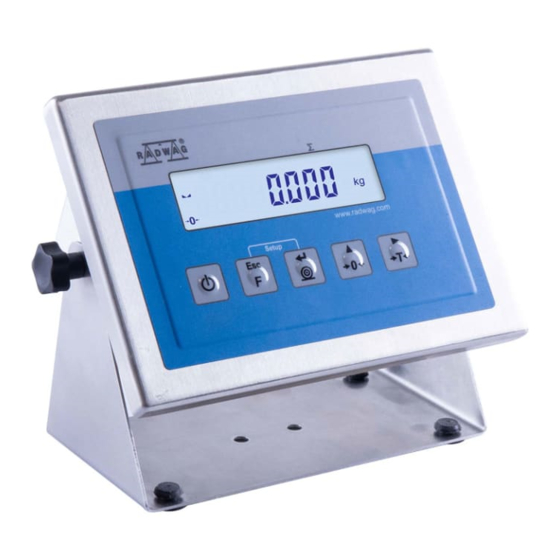
Page 8: Operation Panel
4.4. Operation panel Keys: Press to switch the weighing device on/off – hold the key for about 1 second. Function key, press to change the working mode. Press to send the weighing result to a printer or computer. Press to zero the scale. Press to tare the scale. -
Page 9: Technical Specifications
4.5. Technical specifications Housing Stainless steel Ingres Protection IP 66 / IP 67 / IP 69 -10°C to +40°C Operating temperature Display 100 ÷ 240VAC 50÷60Hz Power supply Optional supply External 12-24VDC OIML Class II and III Max. of verification interval (n) 6000 Maximum signal increase 39mV... -
Page 10: Start-Up
5.2. Start-Up Plug the power cord to the mains. Press button. The key is also used to switch the scale on/off. Display test proceeds (all symbols are backlit for a moment), program name and number is displayed first, mass indication next. 5.3. -
Page 11: Operating The Menu
To return to the home screen press repeatedly. 7. INSTALLER INSTRUCTION The PUE H315 indicator serves as basis of load cell scales. 7.1. Connecting 6-Wire Load Cell Connect 6-wire load cell to the main board following the diagram below:... -
Page 12: Connecting 4-Wire Load Cell
Connecting 6-wire load cells J7 Load cell socket Load cell signals NOTES REF+ SENSE + JP3 not soldered REF- SENSE - JP4 not soldered OUTPUT+ OUTPUT- INPUT+ AGND INPUT- 7.2. Connecting 4-Wire Load Cell Connect 4-wire load cell to the main board following the diagram below:... -
Page 13: Connecting Load Cell's Cable Shield
Connecting 4-wire load cells J7 Load cell socket Load cell signals NOTES REF+ SENSE + JP3 soldered REF- SENSE - JP4 soldered OUTPUT+ OUTPUT- INPUT+ AGND INPUT- 7.3. Connecting Load Cell’s Cable Shield Platforms electrically Platforms connected to connected to indicators’ indicators metal metal... -
Page 14: Factory Setup
8. FACTORY SETUP To access and modify both factory settings and parameters that are made available for a user, run Factory Setup mode. Running Factory Setup mode enables the technician to define the balance. 8.1. Access Switch the weighing device off, to do it press key. -
Page 15: Factory Parameters List
2 - WLC/F, WLC/C2, 4 – WTC, 6 – Medical scale, 7 - Medical scale 0.1.3. 1, 2, 4, 6, 7, 8, 9, 12 (BMI disabled), 8 – PUE C315; 9 – PUE H315; 12 – WLC/C/2. 0.1.4. Gcor 0.9 - 1.1 Gravity correction factor. - Page 16 Autozero range: PrF - value taken PrF, 0.1d, 0.2d, 0.25d, 0.5d, 0.6d, 0.7d, 0.8d, from program-implemented tables; 0.2.b. 0.9d, 1d, 2d, 2.5d, 3d, 0.1d - 10d - value entered directly by 4d,5d,6d, 7d, 8d, 9d, 10d a user. PrF, 0, 0.2s, 0.4s, 0.6s, Autozero time: PrF - value taken from program-implemented tables;...
-
Page 17: Device Defining
0.4.3. Entering correction values for linearity. 0.5. Adnn Additional modules activation Wireless communication module: YES 0.5.1. YES, no - enabled, no - disabled. IN/OUT module:YES - enabled, no - 0.5.2. YES, no disabled. RS485 module: YES - enabled, no - 0.5.3. -
Page 18: Factory Adjustment
While defining balance/scale type, additional parameters are set automatically. These are among many battery type, internal adjustment accessibility, additional modules and communication interfaces accessibility. 8.4. Factory Adjustment 8.4.1. External Adjustment Process Enter factory setup submenu: <P.0.FAct / 0.3.CAL>. Enter <0.3.1.CLE> function, text <UnLoAd> is displayed. ... -
Page 19: Correction Of Start Mass Expressed In Converter's Divisions
8.4.3. Correction of Start Mass Expressed in Converter's Divisions Enter factory setup submenu: <P.0.FAct / 0.3.CAL>. Enter <0.3.4.Stu> submenu, value of start mass expressed in converter's divisions is displayed. Correct the value, to do it use operation panel, next press key to confirm changes. -
Page 20: Corrections
It allows to carry out correct scale calibration/adjustment away from the place of subsequent use. The value of gravity correction must be entered with reference to tables prepared by „RADWAG Wagi Elektroniczne” or calculated using the below formula:... -
Page 21: Optional Extension Modules
9. OPTIONAL EXTENSION MODULES 9.1. Input/Output Module The 637R module expands the PUE H315 indicator functionality by additional 4 inputs and 4 outputs. The module is intended to be mounted inside the indicator. It is equipped with optoisolated inputs and semiconductor outputs, and enables free configuration of both the inputs and the outputs (using indicator menu). -
Page 22: I/O Schematic Diagrams
4WE/4WY 637R module 9.1.2. I/O Schematic Diagrams 4 inputs 4 outputs 9.1.3. Input / Output Signals Overview INPUTS OUTPUTS Wire number Signal Wire number Signal OUT1 OUT2 OUT3 OUT4 COMM_IN COMM_OUT... -
Page 23: 4-20Ma Module
9.2. 4-20mA Module The 636R module expands the PUE H315 indicator functionality by 4-20mA analog output. The module is intended to be mounted inside the indicator. The 636R module is a passive module. The indicator's housing cover features an additional cable gland through which 3-metre cable 2 x 0.25 mm2 is fed, which cable is terminated with isolated wires. -
Page 24: Wiring Diagrams Of 4-20Ma Module
White Brown 9.3. RS485 Module The 635R module expands the PUE H315 indicator functionality by RS485 interface. The module is intended to be mounted inside the indicator. The indicator's housing cover features an additional cable gland through which 3m cable is fed. -
Page 25: Ethernet Module
9.4. Ethernet Module The 635R module expands the PUE H315 indicator functionality by Ethernet interface. The module is intended to be mounted inside the indicator. The indicator's housing cover features an additional M12 4P D-codded connector (Ethernet standard). RS485 635R module 9.4.1. -
Page 26: Diagrams Of Connection Cables
Exemplary assignment of modules on 634R board: Additional modules arrangement 10. DIAGRAMS OF CONNECTION CABLES Indicator - computer cable Indicator - printer cable (EPSON) - Page 27 Indicator - USB adapter cable...
Need help?
Do you have a question about the PUE H315 and is the answer not in the manual?
Questions and answers