Table of Contents
Advertisement
Quick Links
Advertisement
Table of Contents

Related Manuals for RADWAG PUE HX7


Summary of Contents for RADWAG PUE HX7
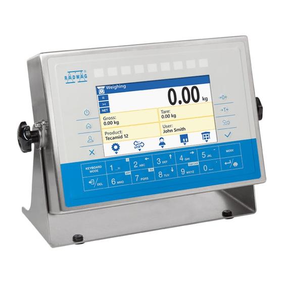
- Page 1 PUE HX7 WEIGHING INDICATOR USER MANUAL ITKU-107-02-02-19-EN...
- Page 2 FEBRUARY 2019...
-
Page 3: Table Of Contents
CONTENTS 1. INTENDED USE............................. 7 2. PRECAUTIONS ............................. 7 2.1. Operation ..............................7 2.2. Battery Power Supply..........................8 3. MAINTENANCE ACTIVITIES ........................8 3.1. Cleaning Stainless Steel Components..................... 8 3.2. Cleaning ABS Components........................9 4. WARRANTY CONDITIONS ........................... 9 5. MECHANICAL DESIGN..........................10 5.1. - Page 4 15.1.5. Printout Interval ........................33 15.1.6. E2R ............................33 15.2. Printer ..............................34 15.2.1. Port............................34 15.2.2. Code Page ..........................35 15.2.3. Prefix, Suffix ..........................36 15.2.4. Record of Measurement Data Onto a USB Flash Drive ............36 15.3. Barcode Scanner ..........................37 15.3.1.
- Page 5 25. WORKING MODES – General Information ....................63 25.1. Running Working Mode........................63 25.2. Working Mode Accessibility......................... 64 26. WORKING MODES - Local Settings ......................64 26.1. Readout .............................. 65 26.2. Save Mode............................65 26.3. Auto Threshold............................ 66 26.4. Result Control ............................. 66 26.5.
- Page 6 34. IMPORT / EXPORT............................ 95 34.1. Data Export ............................95 34.2. Data Import ............................96 35. DIAGRAMS OF CONNECTION CABLES ....................97 36. TECHNICAL SPECIFICATIONS........................ 99 37. ERROR MESSAGES ..........................99 38. ANNEX 01 – Printout Variables ......................100 38.1. Variables List............................. 100 38.2.
-
Page 7: Intended Use
MIN, MAX thresholds. It is operated using 22-key membrane keypad equipped with programmable function keys. PUE HX7 indicator of standard design offers RS232, USB type A, Ethernet, 4 I/O interfaces. Optionally the indicator can be equipped with an internal battery, this allows its operation in places where there is no access to the mains. -
Page 8: Battery Power Supply
2.2. Battery Power Supply PUE HX7 indicator can optionally be supplied by NiMH battery (nickel metal hydride) of 1800 - 2800 mAh capacity. Do not let battery discharge in case of prolonged storage of the device in low temperature. A worn out battery can be replaced only by the manufacturer or by the authorized service. -
Page 9: Cleaning Abs Components
4. WARRANTY CONDITIONS A. RADWAG feels obliged to repair or exchange all elements that appear to be faulty by production or by construction. B. Defining defects of unclear origin and means of their elimination can only be realized with assistance of manufacturer and user representatives. -
Page 10: Mechanical Design
5. MECHANICAL DESIGN 5.1. Dimensions PUE HX7 overall dimensions... -
Page 11: Connectors Arrangement
5.2. Connectors Arrangement PUE HX7 connectors Cable gland for power cord Valve USB 2 M12 4P connector (option) RS232 M12 8P connector RS232 M12 8P connector (option) RS232 M12 8P connector (option) RS485 M12 8P connector (option) Cable gland for a cable of a weighing platform 1... -
Page 12: Pins Assignment
5.3. Pins Assignment Pin1 – NC Pin2 – RxD Pin3 – TxD RS232 Pin4 – NC RS232 (2) Pin5 – GND RS232 (3) Pin6 - +5VDC Pin7 – GNDZ Pin8 – 24VDC Pin1 – OUT1 Pin2 – OUT2 Pin3 – OUT3 Pin4 –... -
Page 13: Inputs / Outputs
5.4. Inputs / Outputs Standard PUE HY10 indicator is equipped with 4 optoisolated inputs and 4 semiconductor outputs (semiconductor relays). Signals are sent via M12 8P connectors. Pin1 – OUT1 Pin2 – OUT2 Pin3 – OUT3 Pin4 – OUT4 4OUTPUTS Pin5 –... -
Page 14: I/O Schematic Diagrams
5.4.2. I/O Schematic Diagrams 4 inputs 4 outputs 6. UNPACKING AND INSTALLATION A. Take the indicator out of the packaging. B. Connect the indicator to a weighing platform, next place the weighing device on a flat and even surface. Keep it far away from any sources of heat. -
Page 15: Operation Panel
• pictogram displayed in a cyclic manner: battery charging. • pictogram displayed continuously: battery charged within 75% - 100% range of permissible voltage. • pictogram displayed continuously: battery charged within 50% - 75% range of permissible voltage. • pictogram displayed continuously: battery charged within 25% - 50% range of permissible voltage. -
Page 16: Home Screen
Keys: Press to switch the device on / off. Press to enter the main menu. Press to log in. Press to cancel the message. Press to zero the scale. Press to tare the scale. Press to change the weighing unit. Press to confirm the message. -
Page 17: Top Bar
Home screen view: 9.1. Top Bar The top bar displays the following information: Working mode name and symbol. Weighing device name. Symbol informing that wireless communication is on. Symbol informing that communication with a USB flash drive is on. Symbol informing that PC keyboard is connected. Symbol informing that printer is connected. -
Page 18: Workspace
9.3. Workspace The workspace is to be found underneath the weighing result window. The workspace comprises 4 programmable widgets. Each working mode features default home screen widgets set. You can customize the screen. For detailed information concerning the workspace read section 'Display'. 9.4. -
Page 19: Menu Keys
Menu view 10.2. Menu Keys Press to enter the main menu. Press to go to the home screen. Press to move one menu level up, or to discard entering parameter modifications. Press to move one menu level up. Press to delete a character when editing numeric and text values. Press to change keyboard mode when editing numeric and text values. -
Page 20: Entering Numeric And Text Characters And Signs
10.3. Entering Numeric and Text Characters and Signs Depending on a type of data entered to indicator's memory the software offers two different edit boxes: • numerical box (for entering part mass values, tare values, etc.). • text box (for entering printout template, universal variable value, etc.). Button functions change depending on the edit box type. -
Page 21: Text Box
Press to enter digit 4. Press to enter digit 5. Press to enter „-” (minus) sign, hold the key for a few seconds. Press to enter digit 6. Press to enter digit 7. Press to enter digit 8. Press to enter digit 9. Press to enter digit 0. - Page 22 Where: Capital letters mode. To change keyboard working mode press key. Keyboard working mode options: - upper-case characters mode, - lower-case characters mode, - digits mode, - arrow keys operation, - bottom bar operation. Press to save project to *.lb file on a USB flash drive. Press to read project saved to *.lb file on a USB flash drive.
-
Page 23: Diacritical Signs Table
Press to exit, the box remains unmodified. Press to confirm the modifications. Press to change keyboard working mode. 10.3.3. Diacritical Signs Table In order to activate diacritical signs table while editing text box it is necessary to press and hold key. -
Page 24: Return To Weighing
10.4. Return to Weighing Introduced modifications are automatically recorded upon return to the home screen. To return to the home screen: • press key repeatedly, keep pressing the key until you see the home screen, • press key, the home screen is displayed immediately. 11. -
Page 25: Log Out Procedure
12.2. Log out Procedure • Go to the home screen, press key, wait for the operators database to open. • Select <Log out> option, the home screen is displayed. 12.3. Permission Levels There are 4 permission levels: Administrator, Advanced Operator, Operator, None. -
Page 26: Zeroing
Load the weighing pan steadily avoiding mechanical shocks. Place the loads centrally on the weighing pan (refer to section 3.6.2 of EN 45501 standard concerning eccentric loading). Do not apply concentrated force (total load in one point). Avoid side loading, in particular side shocks. -
Page 27: Taring
13.3. Taring To determine net weight value, load the weighing pan with a packaging, wait for a stable indication and press key. Zero indication and the following pictograms are displayed: . The weighing device has been tared. Remember not to exceed scale's maximum capacity, i.e. sum of tare weight value and load weight value must be lower than the maximum capacity value. -
Page 28: Weighing Unit Change
13.5. Weighing Unit Change You can change the weighing unit, to do it press key. Options in case when the main unit is [g]: • g (gram), • kg (kilogram), • ct (carat), • lb (pound)*, • oz (ounce)*, • N (newton)*, •... -
Page 29: Setting Min, Max Threshold Using A Programmable Button
• using programmable < Set MIN, MAX> button, • selecting product with set thresholds, • using a digital input. MAX threshold value has to be greater than MIN threshold value. 13.6.1. Setting MIN, MAX Threshold Using a Programmable Button • Enter <Display / Buttons functions> submenu. •... -
Page 30: Weighing Platform Number Change
13.7. Weighing Platform Number Change Optional scale design features an additional weighing platform. It is possible to change the weighing platform number, to do it use programmable button. Platform change is signalled via display of platform number marker, , in the weighing result window. 14. -
Page 31: Usb A Port
Set the transmission parameters in accordance with your local network. <MAC address> parameter is automatically assigned to the weighing device with <Read-only> attribute. If you select option for <DHCP> parameter, the remaining transmission parameters are given <Read-only> attribute. 14.3. USB A Port USB port of type A is intended for: •... -
Page 32: Port
15.1.1. Port Parameter allowing you to set port for communication between the weighing device and the computer. Available ports: RS232 (1) RS 232 ports (M12 8P connectors). RS 232 (2) * RS 232 (3) * Ethernet Ethernet port (RJ45 connector). *) –... -
Page 33: Continuous Transmission
15.1.4. Continuous Transmission Parameter allowing you to activate 'scale' - 'computer' continuous transmission. In order to send the content of <Weighing printout template> to a computer continuously you must activate <Continuous transmission> parameter. Procedure: • Enter <Peripherals / Computer / Continuous transmission> submenu and set respective value. -
Page 34: Printer
USB port of type A (M12 4P connector). Ethernet port (RJ45 connector). used for connecting a network printer Ethernet or a computer with RADWAG-designed program, e.g. RAD KEY. USB port of type A. used for connecting a USB flash drive in order Pendrive to print weighings to a text file. -
Page 35: Code Page
IP Address: IP address of the scale. Port: number of port for transmission protocol. Ethernet Timeout [ms]: time delay - time interval for disconnection, counted from the moment of the most recent command sent from the peripheral device to which the weighing device is connected. *) –... -
Page 36: Prefix, Suffix
15.2.3. Prefix, Suffix Prefix and suffix are controlling codes (given in a hexadecimal format) sent to a printer at print start - <Prefix> parameter, and at print end - <Suffix> parameter. Sending these codes allows to control globally information and actions carried out at the beginning and/or at the end of each printout sent from a weighing device to a printer. -
Page 37: Barcode Scanner
15.3. Barcode Scanner The scale can integrate with a barcode scanner. The barcode scanner is used to facilitate quick search for database records. Enter <Communication> submenu and set baud rate for a barcode scanner (by default 9600b/s). For detailed description of 'scale' - 'barcode scanner' communication read ANNEX 04 of this user manual. -
Page 38: Prefix, Suffix
Parameter allowing you to edit <Prefix> and <Suffix> in order to provide synchronization of the scale program with a barcode scanner. In RADWAG-adopted standard, the prefix is 01 sign (byte) hexadecimal format, the suffix is 0D sign (byte) hexadecimal format. -
Page 39: Test
Packaging Name, Code. Lot number Batch number *) - <Filtering> submenu hidden. Function inactive. **) - <Filtering> submenu hidden. Function active. 15.3.7. Test Parameter allowing you to verify if operation of a barcode scanner connected to a scale is correct. Procedure: •... -
Page 40: Bottom Text Area Template
Enter <Communication> submenu and set baud rate, mind that the set value must be accordant with the additional display (115200b/s). 15.4.2. Bottom Text Area Template Additional display features text area for extra information such as date, tare value etc. Displayed data content is set using the weighing device. Procedure: •... -
Page 41: Linear
Available diode bar graph types: Linear, Weighing thresholds signalling, Checkweighing. 16.2.1. „Linear” Bar graph of this type provides you with a linear presentation of the weighing range. 16.2.2. „Weighing thresholds signalling” Bar graph of this type shows where Min and Max thresholds are (providing that they have been declared). - Page 42 • If the measured mass value is higher than 1/3 and lower than 2/3 of MIN- MAX range, then the centre green field lights up. • If the measured mass value is higher than 2/3 of MIN-MAX range and lower than MAX value, then the centre green field lights up along with the field on its right.
-
Page 43: Printouts
17. PRINTOUTS <Printouts> submenu allows you to: • define template for header, GLP and footer printout, • define report templates: adjustment, dosing, formulations. • create 10 non-standard printouts. 17.1. Print Mode: Header – GLP Printout - Footer Printout comprises 3 basic sections: Group of parameters allowing you to declare variables that are to be Header printed on a header printout. - Page 44 2. To print variables comprised within Header and/or Footer section which are enabled for printing and marked with pictogram, press respective programmable button: < Header printout> and/or < Footer printout>. For detailed procedure informing you how to program buttons, read section 19.2. Variables description Variable Description...
-
Page 45: Non-Standard Printouts
Printout examples: Header GLP printout Footer 17.2. Non-Standard Printouts The program allows you to design 10 non-standard printouts. Each of them can consist of approximately 1900 characters (letters, digits, special signs, spaces), including: • fixed texts, • variables conditioned by a particular working mode and operator needs (mass, date, checkweighing thresholds). -
Page 46: Dosing Report
Variables description Variable Description Project Project name (31 characters maximum). Adjustment type Performed adjustment type. Operator Logged-in operator name. Project Project name printout. Date Adjustment performance date. Time Adjustment performance time. Scale S/N Serial number of the scale. Platform number Number of platform via which the adjustment was carried out. -
Page 47: Formulation Report
Difference between the sum and the value of expected target weight. 18. INPUTS / OUTPUTS Standard version of PUE HX7 indicator is equipped with 4 inputs and 4 outputs. In order to set inputs and outputs enter: < / Inputs/Outputs> submenu. -
Page 48: Input Setup
18.1. Input Setup • Enter <Inputs / Outputs> submenu. • Select <Inputs> parameter and edit respective input, list of functions that can be assigned to the input is displayed. Input functions list is identical like key functions list, read section 19.2. •... -
Page 49: Display
By default all functions are assigned with <None> value. For detailed description on how to set MIN, MAX thresholds refer to section 13.6. 19. DISPLAY You can customize the home screen and the displayed data. Customization concerns the workspace (fields 1, 2, 3, 4) and the bottom area (5) featuring programmable buttons with functions assigned to numeric keys of the operation panel: In order to customize the screen go to <... - Page 50 <Workspace components> submenu for a field comprising <Label> widget features the following options: Information Enter this parameter to read info on selected widget type and dimensions. Settings Enter this parameter to specify which widget-assigned data is to be displayed. Enter this parameter to delete the widget. Upon entering, a respective warning Delete is displayed: <Delete?>.
-
Page 51: Text Box
Gross Part mass Reference mass Status Formulation Ingredient - Default label settings. 19.1.2. Text Box Field displaying weighing-related information. As an operator you can freely program the field content (texts and variables of line 1 and line 2). For detailed information regarding text box read section 10.3.2. - Page 52 Additionally it shows: • position of Min and Max thresholds in <Weighing>, <Parts Counting>, <Percent weighing> working modes. • position of dosing thresholds in dosing process (read section 30.3 of this manual). • position of percent weighing range in formulation process (read section 31.4 of this manual).
-
Page 53: Keys
Min=1600g Max=1800g • Visualisation of mass value higher than MAX value: Min=1600g Max=1800g MAX threshold value has to be greater than MIN threshold value. For detailed description on how to set MIN, MAX thresholds refer to section 13.6. 19.2. Keys Programmable numeric keys (0 - 9). - Page 54 Set tare Set MIN and MAX Print header Print footer Statistics: Zero Statistics: Print Statistics: Print and zero Edit labels quantity Edit C labels quantity Edit lot number Edit batch number Edit universal variable 1 Edit universal variable 2 Edit universal variable 3 Databases Reports Select operator...
-
Page 55: Default Screen Settings
Determine part mass Assign reference sample Reference sample quantity - 5 pcs Reference sample quantity – 10 Reference sample quantity – 20 Reference sample quantity – 50 Reference sample quantity – 100 Set reference sample mass Determine reference sample mass Process start Process stop Process pause... -
Page 56: Permission Levels
20. PERMISSION LEVELS <Permissions> submenu is available for operators logged as Administrator. This group of parameters allows you to determine access rights for particular operators. In order to set permission levels enter < / Permissions> submenu. 20.1. Anonymous Operator Parameter allowing you to assign unlogged weighing device operator (so called anonymous operator) with permission level. -
Page 57: Databases Edition
When <None> option is set, all unlogged operators can edit printouts. 20.4. Databases Edition Parameter allowing you to set permission levels enabling particular operators to edit the following databases: products, formulations, packaging, customers, universal variables. Procedure: • Enter <Permissions / Databases edition> submenu. •... -
Page 58: Units Availability
In order to set units enter < / Units> submenu. Accessibility of particular units is conditioned by weighing device status; i.e. it depends on the fact whether the given scale is verified or not. 21.1. Units Availability Parameter allowing to declare which units are to be accessible upon pressing key. -
Page 59: Custom Units
21.4. Custom Units Option available for non-verified scales exclusively Parameter allowing you to declare two custom units. Displayed custom unit value is a result of calculation, where obtained in the course of measurement weight value is multiplied by a multiplier determined for this particular custom unit. -
Page 60: Display Brightness
Procedure: • Enter <Misc / Sounds> submenu and set respective option. Where: Sound signal enabled. Sound signal disabled. 22.3. Display Brightness Parameter allowing you to change display brightness, the brightness can be changed within 0% - 100% range. Procedure: • Enter <Misc / Display brightness> submenu and set respective value. Available values: 0%, 10%, 20%, 30%, 40%, 50%, 60%, 70%, 80%, 90%, 100% (set by default). -
Page 61: Backlight Standby Time
22.5. Backlight Standby Time Parameter allowing you to set time interval, in [min], after which the screen goes black. Procedure: • Enter <Misc / Backlight standby time> submenu and set respective value. Available values: None (set by default), 0.5, 1, 2, 3, 5. 22.6. -
Page 62: External Adjustment
23.1. External Adjustment External adjustment is carried out using an external mass standard of the right accuracy and weight value, which value depends on scale type and capacity. Correction is carried out semi-automatically, successive process stages are signalled with prompts. Procedure: •... -
Page 63: Adjustment Report
23.4. Adjustment Report Adjustment report is automatically generated at the end of each adjustment process, next it is sent to port selected for <Peripherals / Printer>. To declare report content go to <Printouts / Adjustment report> submenu. For instruction on how to declare adjustment report settings read section 'Printouts'. -
Page 64: Working Mode Accessibility
• Select the working mode you need to operate, the home screen is displayed automatically, wherein the top bar of the screen features pictogram of the selected mode. 25.2. Working Mode Accessibility You can declare which working modes are to be accessible for an operator upon pressing key. -
Page 65: Readout
On-screen button (working mode parameters) that is to be found in each working mode home screen, provides direct access to settings of the given working mode. 26.1. Readout Readout submenu comprises functions allowing you to adjust your weighing device to ambient conditions of a given workstation. Enter this parameter to adjust your weighing device to ambient conditions. -
Page 66: Auto Threshold
Automatic printout of the last stable weighing result Automatic last stable detected upon the weight value gets below <Auto threshold>. Manual printout of each weighing result, where the weight Semi-automatic each stable value is above -LO- threshold; this option requires awaiting for the stable weighing result. -
Page 67: Autotare
26.5. Autotare Autotare function allows you to quickly determine net weight for loads with different tare values, which loads are measured one after another. When <Autotare> function is on, the operation cycle takes the following steps: • Make sure that the weighing pan is empty and press zeroing key. •... -
Page 68: Statistics
None Manual printout of C label *, performed upon pressing either button. Automatic printout of C label, triggered upon exceeding of the total mass value Mass of single labels, set in <Threshold> parameter. Automatic printout of C label, triggered upon exceeding single labels quantity, Number set in <Threshold>... -
Page 69: Working Mode - Weighing
Where: Global Update of statistical data carried out globally. Update of statistical data carried out individually for each product, either Product weighed or selected from the database. 27. WORKING MODE – WEIGHING <Weighing> is a standard working mode enabling you to carry out the weighing operation along with record of the result to the database. -
Page 70: Working Mode - Parts Counting
28. WORKING MODE – PARTS COUNTING <Parts counting> is a working mode enabling you to determine quantity of small pieces of the same mass, which determination is done on the basis of reference weight value of single piece, either determined using the weighing device or taken form the database. -
Page 71: Function Of Automatic Correction Of Reference Sample Mass
28.2.1. Function of Automatic Correction of Reference Sample Mass <ACAI> is a specific function enabling you to correct weight value of a single piece by means of the weighing device program. Procedure: • Enter <Working modes / Parts counting / ACAI> submenu and set respective option. -
Page 72: Setting Reference Sample Mass By Entering Mass Of A Single Part
Total mass of all the pieces loaded onto the weighing pan must not be lower than value declared in „Minimum reference sample mass” parameter. Unless this condition is met, the weighing device displays a message: <Sample mass too low>. 28.3. Setting Reference Sample Mass by Entering Mass of a Single Part •... -
Page 73: Setting Reference Sample Mass By Acquiring Mass Of A Single Part From Database
Total weight value of all parts loaded onto the weighing pan cannot be lower than the value determined by „Minimum reference sample mass” parameter. Unless this condition is met, weighing device displays message: <Sample mass too low>. Single part mass must be equal or greater than 0.1 of the reading unit. -
Page 74: Home Screen
29.1. Home Screen 29.2. Local Settings In order to access local settings, press operation panel key to which < Working mode parameters> pictogram is assigned: Readout For detailed description read section 26.1. Save mode For detailed description read section 26.2. Auto threshold For detailed description read section 26.3. -
Page 75: Reference Sample Mass Entered To The Weighing Device Memory
29.4. Reference Sample Mass Entered to the Weighing Device Memory • Press button (Set part mass), <Set reference sample mass> edit box featuring an on-screen keyboard is displayed. • Enter respective value and press key to confirm changes. • Now (instead of weight value of the measured load) difference between values of loaded mass and reference mass is displayed in [%]. -
Page 76: Local Settings
30.2. Local Settings In order to access local settings, press operation panel key to which < Working mode parameters> pictogram is assigned. Procedure: • Enter < / Working modes / Dosing> submenu. • Select <Dosing mode> parameter and set one of the dosing modes: Manual dosing Manual dosing with MIN, MAX thresholds. -
Page 77: Automatic Dosing Procedure
Enter to correct the dosed mass, this function allows to optimise the dosing process, change of pressure of dosed material in the silos is accounted for. Parameters: Constant correction – specifying global (constant) value of correction to be applied during each process; Maximum Dosing correction correction –... - Page 78 When: 1. Dosing outputs are declared incorrectly (e.g. lack of active dosing output) the following message is displayed: <Dosing outputs determined incorrectly>, next the process is cancelled. 2. The weighing result is unstable then the following message is displayed: <Unstable weighing result>. The process status changes to PS=Pause and remains so until stable weighing result is obtained.
- Page 79 Buttons that are assigned to operation panel keys: Local parameters (button inactive during the ongoing process). Product selection. Process start. Process stop. Breakdown stop. Bar graph functioning, 1-stage automatic dosing: • Visualisation of mass value lower than the value of [DT2] threshold: DT2=1800g DT1=0g •...
-
Page 80: Manual Dosing Procedure
• Upon exceeding the value of dosing threshold, dosing outputs are activated and PS=OK process status is displayed. • In case of active time delay, countdown of declared time starts. • After countdown completion, PS=Completed status is displayed (process completed). Blinking pictogram is turned off. -
Page 81: Dosing Process Report
Workspace data: Value of low threshold of manual dosing. Value of max threshold of manual dosing. Process status, the status takes the following values: -3.000kg – amount left to be dosed; OK – target dosing mass comprised between MIN and MAX thresholds; Pause –... -
Page 82: Working Mode - Formulations
Status Completed ---------------------------------------- Signature ........Report on each completed process is saved to <Dosing reports> database, the file name is a combination of date and hour of process completion and of process status (list of dosing report data – read section 33.3.3). 31. -
Page 83: New Formulation
31.3. New Formulation • Enter < / Databases / Formulations> submenu. • Press operation panel key to which pictogram (add) is assigned. New record is automatically edited. For list of new formulation data read section 32.6.3 of this manual. • Enter <Ingredients> submenu, add formulation ingredients one by one, do it by pressing key to which pictogram (add) is assigned. -
Page 84: Formulation Procedure
31.4. Formulation Procedure • Select the formulation, do it by pressing key to which pictogram (select formulation) is assigned. • Save general parameters of 'Formulations' mode to scale memory, the parameters are to be found upon pressing a key to which pictogram is assigned. - Page 85 Workspace data: Low deviation value. High deviation value. Process status, the status takes the following values: -3.000kg – amount left to be weighed; [1/3] – cycle 1 of 3; OK – target mass obtained; Pause – process inhibited: a) by means of (pause) button, to restart the process press button, b) stable weighing result is awaited for, Taring –...
-
Page 86: Formulation Report
In the case of trying to accept unstable weighing result, the following message is displayed: <Unstable measurements>. • After weighing of the last ingredient, PS=Completed status is displayed (process completed). • New formulation process may begin. 31.5. Formulation Report Formulation report is automatically generated at the end of each formulation process, next it is sent to port selected for <Peripherals / Printer>. -
Page 87: Database Export
Customers Labels Universal variables In order to configure databases, enter < / Databases> submenu. Databases editing is available for operators logged as Administrator. 32.1. Database Export Export of weighing device databases carried out using a USB flash drive. Procedure: • Enter selected database. •... -
Page 88: Database Import
32.2. Database Import Import of weighing device databases carried out using a USB flash drive. Procedure: • Enter selected database. • Activate function keys, to do it press key. • Connect the USB flash drive to the USB A port. •... -
Page 89: Databases Edition
32.6. Databases Edition 32.6.1. Operators Operators database features list of users permissioned to operate the weighing device. List of parameters defined for an operator: Name Operator name (43 characters maximum). Code Operator code (15 characters maximum). Operator password, used in the course of logging in operation Password (15 characters maximum). -
Page 90: Formulations
Price Unit price of a product. VAT value given in [%]. Shelf-life time in days Shelf-life time of a product (number of days). Label Template of a single label assigned to a product. C Label Template of a cumulative label assigned to a product. Manual mode for entering ingredient mass (ingredient is not Weight entered manually weighed). -
Page 91: Customers
32.6.5. Customers Customers database features a list of names of customers for whom the measurements are carried out. List of parameters defined for a customer: Name Customer name (43 characters maximum). Code Customer code (15 characters maximum). Tax identification number (15 characters maximum). Address Customer address (43 characters maximum). -
Page 92: Reports
Alibi Alibi xxxxxx.ali Dosing reports Dosing reports xxx xxx.dos Formulations reports xxxxxx.for Where: xxxxxx – weighing device serial number. Files can be read using ALIBI Reader, PC software designed by RADWAG. You can download the software from RADWAG website: www.radwag.pl. -
Page 93: Deleting Reports
33.2. Deleting Reports N/a in case of Alibi reports database • Enter reports database. • Activate function keys, to do it press key. • Press key to which pictogram (delete all records of report database) is assigned. Message <Delete all records?> is displayed. •... -
Page 94: Alibi
33.3.2. Alibi Each weighing result sent from the weighing device to a printer is saved to Alibi report. You can preview data of particular weighings. List of parameters defined for a completed weighing Date Performed weighing date. Time Performed weighing time. Result Weighing result given in specific unit (%, pcs). -
Page 95: Formulations
33.3.4. Formulations Formulation report is generated automatically after completion of each formulation process. You can preview data for particular reports. Formulation performance status. Status values: Ongoing, Aborted, Status Completed. Start date Formulation start date. End date Formulation end date. Formulation Performed formulation name. -
Page 96: Data Import
Data stored in files of weighings and Alibi reports can be read using special RADWAG-designed PC software. 34.2. Data Import <Import> function allows you to copy databases and operator parameters between weighing devices of the same series. -
Page 97: Diagrams Of Connection Cables
35. DIAGRAMS OF CONNECTION CABLES Indicator - computer cable Indicator - printer cable (ZEBRA) Indicator - printer cable (EPSON) - Page 98 Indicator - IN/OUT cable Indicator – barcode scanner cable (LS2208) Indicator – PRINT, TARE, ZERO, STOP cable „Scale-Ethernet” cable standard network cable terminated with RJ45 connectors on both ends.
-
Page 99: Technical Specifications
36. TECHNICAL SPECIFICATIONS Housing Stainless steel Ingress protection IP68 / IP69 Display 7’’ colour Power supply 100-240VAC 50-60Hz Optional power supply Internal battery Operating temperature -10 °C ÷ 40 °C Maximum signal gain 19.5 mV Maximum impedance of load cell 1200 Ω... -
Page 100: Annex 01 - Printout Variables
38. ANNEX 01 – Printout Variables 38.1. Variables List Each defined variable must be inserted in between curly bracket: {x}, where x – variable number. List of variables defining non-standard printout templates and data displayed within the workspace. Description Standard printout in an adjustment unit Standard printout in a current unit Date Time... - Page 101 {37} Statistics: Standard deviation {39} Universal variable: Value {41} Batch number: Value {45} Parts counting: Reference sample quantity {49} Universal variable: Name {50} Product: Name {51} Product: Code {52} Product: Name 2 {53} Product: Code 2 {54} Product: Mass {55} Product: Price {56} Product: Tare...
-
Page 102: Variables Formatting
{126} Formulation report: Sum {127} Formulation report: Difference {128} Formulation report: Status For {39}, {49} variables, each database entry (1,2-n) must be formatted as follows: Entry 1 - {39:1}, {49:1}, Entry 2 - {39:2}, {49:2}, etc. 38.2. Variables Formatting You can format numeric variables, text variables and dates which are to be printed or displayed in the grey workspace. - Page 103 Date separator separating days, {2:yyyy/MM/dd} – Current date in format: months and years. year/month/day. Date separator separating day, {2:yyyy.MM.dd} – Current date in format: month year, time year.month.day. separator separating hour, {3:HH.mm.ss 24H} – Current time in format: minute and second. hour.minute.second.
-
Page 104: Annex 02 - Label Template
39. ANNEX 02 – Label Template Label template can be created: • via scale, using available variables, • via Label Editor R02 PC software. For detailed description concerning creation of label template via PC software, read user manual of „Label Editor R02”. -
Page 105: Assigning A C Label With A Template To A Product
39.4. Assigning a C Label with a Template to a Product • Enter <Databases / Products> submenu and select respective entry. • Enter <C Label> parameter, label database with list of existing C labels is displayed. • Select respective label, it is automatically assigned to a product. 39.5. -
Page 106: Annex 04 - Barcode Scanner Configuration
5. A special protocol is required in order the code be received by RADWAG equipment. It is required to program an appropriate prefix and suffix.
Need help?
Do you have a question about the PUE HX7 and is the answer not in the manual?
Questions and answers