Table of Contents
Advertisement
Quick Links
Service manual
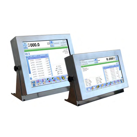
Weighing terminal
PUE 5.15
PUE 5.19
For cooperation with strain gauge load cells
Manual number:
ITKU-84-02-10-13-PL
M A N U F A C T U R E R O F E L E C T R O N I C
W E I G H I N G E Q U I P M E N T
RADWAG Wagi Elektroniczne, 26 – 600 Radom, Bracka 28, POLAND
Phone: +48 (0-48) 38 48 800, fax. +48 (0-48) 385 00 10
Sales department: +48 (0-48) 366 80 06
export@radwag.com
www.radwag.com
Advertisement
Table of Contents

Related Manuals for RADWAG PUE 5.15


Summary of Contents for RADWAG PUE 5.15
- Page 1 M A N U F A C T U R E R O F E L E C T R O N I C W E I G H I N G E Q U I P M E N T RADWAG Wagi Elektroniczne, 26 – 600 Radom, Bracka 28, POLAND Phone: +48 (0-48) 38 48 800, fax. +48 (0-48) 385 00 10 Sales department: +48 (0-48) 366 80 06 export@radwag.com...
- Page 2 OCTOBER 2013 - 2 -...
-
Page 3: Table Of Contents
Table OF CONTENTS 1. INTENDED USE ......................... 5 2. PRECAUTIONS MEASURES ..................... 5 3. WARRANTY CONDITIONS ....................6 4. UNPACKING AND INSTALLATION ................... 6 5. TERMINAL CONSTRUCTION .................... 7 5.1. Overall dimensions ...................... 7 5.2. Description of ports ..................... 9 6. - Page 4 16. ERROR MESSAGES .......................52 17. CABLES DIAGRAMS ......................52 17.1. USB cable for a printer .....................52 17.2. Cable RS232 for EPSON, CITIZEN printer ..............53 17.3. Cable RS232 terminal – computer ................53 17.4. Cable RS232, RS485 ....................53 17.5. Ethernet cable ......................54 18. EXTRA MODULES SPECIFICATION ................54 18.1.
-
Page 5: Intended Use
1. INTENDED USE PUE 5.15, PUE 5.19 terminals are designed for scales that work with strain gauge load cells. The terminals’ housing is made of stainless steel. PUE 5.15, PUE 5.19 are intended to be used in industry. A big colourful screen of the terminal with a touch panel makes the software operation much more comfortable since there is no need to use a keyboard. -
Page 6: Warranty Conditions
3. WARRANTY CONDITIONS A. RADWAG company will repair or replace the elements that turn out to be faulty in terms of production or construction. B. Agreeing on the ways of any defects elimination in case of their unclear origin can be done only in presence of the producer and the user representatives. -
Page 7: Terminal Construction
5. TERMINAL CONSTRUCTION 5.1. Overall dimensions Fig.1 PUE 5.15 terminal dimensions - 7 -... - Page 8 Fig.2 PUE 5.19 terminal dimensions - 8 -...
-
Page 9: Description Of Ports
5.2. Description of ports Fig.3 Back board view of PUE 5.15, PUE 5.19 Cable gland of the strain gauge load cell (x4items) USB M12 4 pin port RS232 port 4WY port (option) Cable gland for the cable RS485 (option) Panel USB port... - Page 10 Ethernet: RJ45 port, USBx2: M12 4pin port, USBx2: type A panel port • Depending on the version of the terminal PUE 5.15, PUE 5.19 it is possible to optionally equip it with the following ports: Extra weighing platforms Ethernet cable through the PG9 cable gland...
-
Page 11: Weighing Module Mw-04
Pin1 – Vcc Pin2 – D- Pin3 – D+ Pin4 – GND Ethernet RJ45 Standard RJ45 USB panel USB A Standard USB A Pin1-WE1 Pin2-WE2 Pin3-WE3 Pin4-WE4 Pin5-COMM Pin6-+24VDC Pin7-GND Pin1-WY1 Pin2-WY2 Pin3-WY3 Pin4-WY4 Pin5-COMM Pin6-+24VDC Pin7-GND Caution: Depending on how many extra modules have been installed the number of ports and cable glands and their position may change. -
Page 12: Configuration Of Com Serial Ports
Fig.4 Interfaces module TOP view 7.1. Configuration of COM serial ports Chart below presents assignation of COM ports detectable by Windows operating system to proper ports of a terminal back board. Caution: • Weighing module MW-04 communicates with a PC module by COM6 •... -
Page 13: Rs485 - Com2
Socket Pins view RS232 RS232 – COM3 RS485 RS485 – COM2 RS232 RS232 – COM5 MW-04 module (J6 on RS232 – COM6 334Rxxxx board) 7.2. RS485 – COM2 COM2 can be configured as RS485 or RS232. By defult it is configured as RS485 (standard positioning of the ports). -
Page 14: Mwmanager Start-Up
Caution: 1. The manual complies with 1.0.3.1 version of „MwManager” program (and the following versions) and with weighing module MW-04 – version 1.1 and following versions. 2. Pressing the Save button saves all the changes in the weighing module. All temporary parameters that haven’t been saved permanently into the module are marked with red colour. -
Page 15: Parameters Edition
9.2. Parameters edition Parameters edition depends on a parameter type, to do it: • Press button and choose a demanded menu out of a list. • Click a window of a given parameter and use a program keyboard to write a value. •... - Page 16 Functions of the key buttons: Confirmation of a change of a parameter Canceling change of a parameter Scrolling the list of available parameter values up Scrolling the list of available parameter values down Information button, displays information about settings of a given parameter Saving the settings: Changes will be stored in a weighing module after Save button...
-
Page 17: Weighment Display
• You will see the confirmation message: • Press <OK>, • Changes have been saved in a permanent storage of a weighing module. If any setting changes will be done but not saved the user may press Refresh button to view the present settings. 9.3. -
Page 18: Application Settings
- weighing unit - weighing platform number Functions of the key buttons: Zeroing Taring Selection of a weighing platform (when a module works with more than one platform). Green colour indicates the presently operated platform. Caution: Zeroing and taring function is available for a presently operated platform. 9.4. - Page 19 Fig.7 Connection settings window Press MW-04 button to connect to module MW-04. This button is located in a “device selection” bookmark. Description: The device to which the user wants to connect Device selection weighing module MW-01 weighing module MW-04 To be selected in case of cooperation with weighing module MW-04 - 19 -...
- Page 20 Selection of interface connection with a weighing module Connection types RS 232 Connection via RS232 port TCP/IP Connection via Ethernet network RS 485 Connection for RS 485 network Offline mode is used for saving and edition of all indispensable Offline parameters.
-
Page 21: Language
Description of buttons: Connecting with a module. After the connection has been established the button function switches from “Connect” to “Disconnect” and its colour changes from red to green. Disconecting from a module. In case of accidental disconnection the button’s function switches to „Connect” and the colour changes to red again. -
Page 22: Other
9.4.3. Other Other button , which is located in application settings bookmark , lets to operate other available options. Fig.9 Other options window „Carry out a test connection during the application starting procedure” – this option enables the program to automatically connect with the weighing module. -
Page 23: Parameters
After setting the options press Save button in order to save introduced changes. 9.5. Parameters Parameters bookmark contains user parameters, weighing module communication parameters, INPUT/OUTPUT functions and a preview of available scales platforms and A/D converters. 9.5.1. User parameters User parameters button , which is located in Parameters bookmark opens a user parameters window. -
Page 24: Communication Settings
Beep Sound signal (unavailable for MW-04 module) Median filter value settings Median filter None – median filter turned off The moving average filter speed settings Filter None – filter turned off Current unit Change of a current unit Caution: When few platforms are being operated by MW-04 module at one time, only parameters for a selected platform are displayed and can be edited . - Page 25 Fig.11 Ethernet communication parameters window Description of fields: IP address Device IP address, by default 192.168.0.2 Subnet mask Ethernet subnet mask, by default 255.255.255.0 Default gateway Ethernet default gateway, by default 192.168.0.1 Port TCP communication port, by default 4001. Number of seconds of the device inactivity that results in Timeout disconnection of the device, number of seconds ranges from 0 to 300 [s].
-
Page 26: Input/Output Functions
RS485 communication interface speed transmission. By default Speed RS485 57600 bps To save changes of communication parameters it is necessary to execute restaring procedure of a weighing module. One must remember that new parameters have to be written in the Connection settings window See point 9.4.1 of this manual. - Page 27 Fig. 13 Inputs/Outputs configuration window - 27 -...
-
Page 28: Available Platforms Preview
• Inputs configuration Inputs functions: Inactive Input None Selected platform taring Taring Selected platform zeroing Zeroing Start of a dosing process for a selected platform Dosing Start Stop of a dosing process for a selected platform Dosing Stop • Oututs configuration Outputs functions: Inactive Output None... -
Page 29: Available A/D Converters Preview
The button , which is located in Parameters bookmark opens scales windows preview of all the scales being operated by MW-04 module. For each platform the following information is displayed: A/D converter(s) divisions, calibration coefficient and an input mass. Caution: Window preview depends on the number of A/D converters, the number of platforms connected to the device and their configuration. -
Page 30: Functions
Caution: Window preview depends on the number of A/D converters, the number of platforms connected to the device and their configuration. Fig.15 A/D converter divisions preview window 9.6. Functions Dosing, checkweighing, state and Input/Output simulations are set in functions bookmark 9.6.1. - Page 31 Fig.16 Dosing parameters window • Bargraph Dosing window contains a graphic bar that visualizes mass readout within a weighing range of a weighing module. Bargraph can be graduated upto 120% of an extreme dosing threshold if a fine dosing threshold option has been selected. If a fine dosing threshold option is turned off then the bargraph is graduated in accordance with a fast dosing threshold.
- Page 32 Fig.18 Graduation of bargraph for a quick and fine dosing threshold Fig.19 Bargraph for a small amount of mass with a graduation option turned off Fig.20 Bargraph for the same amount of mass with a graduation option turned on • Dosing parameters Fig.21 Dosing parameters settings window Depending on the need dosing process may be carried out in two stages or one stage.
- Page 33 Fields description: Fast dosing threshold Output number Mass value which finishes the 1 stage Choice of an output or few outputs of a dosing process. active during the 1 dosing process (switching on to the second stage, not in stage (for a presently operated case of one-stage dosing process.) weighing platform).
-
Page 34: Checkweighing
• Dosing simulation There are Stop dosing and Start dosing buttons in the bottom part of a dosing simulation window. No matter what functions have been assigned on Inputs, these buttons enable dosing process start and stop. 9.6.2. Checkweighing Turning on option and pressing button opens checkweighing settings window for a presently selected weighing platform. -
Page 35: Input/Output State
Caution: Checkweighing signalling is available after the Output functions have been set. See point 9.5.3 of this manual. 9.6.3. Input/Output state Window of Inputs signaling which also allows configuration of Outputs state opens upon activation of functions option and pressing Input/Output state button. -
Page 36: Weighment
10. WEIGHMENT Put a product to be weighted on a scales pan. Read a measurement when a marker has been displayed. Caution: In case of cooperation of weighing module MW-04 with more than one weighing platform the user must select a correct platform in a weighment display in order to get the correct mass reading. -
Page 37: Scales Zeroing
• avoid side loads, especially side shocks: 10.2. Scales zeroing In order to zero mass readout of a presently selected platform the user has to press button which is to be found in a weighment display of a „MwManager” program (the top right hand corner) or he has to initiate zeroing function defined for a given input (See point 9.5.3 of this manual). -
Page 38: Weighment For Dual Range Scales
While using tare function the user has to pay attention to maximal weighing range. It cannot be exceeded. The readout which is a sum of tarred mass will be displayed after the load and the package have been taken off. Minus sign will be seen in front of a displayed value. -
Page 39: Scales Parameters
Fig. 25 User parameters window Possible choices: • When a main unit of scales is [kg], the user can select following units: [kg, lb, oz, ct, N, g], for verified scales [lb, oz, N] are unavailable; • When a main unit of scales is [g], the user can select following units: [g, kg, lb, oz, ct, N], for verified scales [lb, oz, N] are unavailable;... -
Page 40: Autozero Function
11.1. Autozero function For ensuring accurate balance readaouts „AUTOZERO” function has been introduced. This function automatically controls and corrects zero readouts. When this function is active several measuring results are compared at regular intervals. If value differentiating these results is lower than declared AUTOZERO range, e.g. -
Page 41: Filter
Procedure: • Enter user parameters window • Select <Median filter> parameter, press • Select a desired setting out of the available list Available parameters: None - medain filter turned on 0.5, 1, 1.5, 2, 2.5 - medain filter turned off 11.3. -
Page 42: Checkweighing
12. CHECKWEIGHING Checkweighing is a function that enables precise weighment of a sample for which minimum and maximum weighing threshold, so called checkweighing thresholds, have been determined (LO – to little mass of the sample, HI – to big mass of the sample, OK – correct mass of the sample). These states are presented through light signaling or through steering of peripheral devices systems. -
Page 43: Min/Max Threshold
• Press button to close dialog window • Press Save button to save introduced changes into a permanent storage of a module. 12.2. MIN/MAX threshold <MIN threshold> parameter determines net mass threshold of a checkweighing function. For the determined net mass the state swaps between Min and OK. -
Page 44: Dosing
• Press button to close a dialog window, • Press Save button to save introduced changes into a permanent storage of a module. 13. DOSING Dosing function enables precise weighment of a given product up to desired value. <Fast dosing threshold> parameter stands for net mass value of fast (rough) dosing below which one or more outputs are active. - Page 45 • Enter a threshold value • Press button to close the dialog window, • Press Save button to save introduced changes into a permanent storage of a module. • Changes will be confirmed with the following message: • If any threshold values will be changed but not saved than present settings can be read out, to do it the user has to use a Readout button.
-
Page 46: Parameters Saved To File
Caution: Description of a dosing function and its parameters are to be found in the point 9.6.1 of this manual. 14. PARAMETERS SAVED TO FILE „MwManager” program allows saving set parameters into *.sav file format. This function can be useful when saving module settings as a safety copy in case of a weighing module breakdown. -
Page 47: Save To File
14.1. Save to file Procedure: • Press Save to file button after the weighing module parameters have been set • In an operating system window select file destination folder and press Save button. Fig.28 „Save as” system window • The following message will inform about correctly saved parameters. - 47 -... -
Page 48: Read From File
Caution: Preview of an operating system window depends on the installed operating system therefore it may differ from the one presented in Fig.28. 14.2. Read from file Procedure: • In order to read the parameters press Read from file button •... -
Page 49: Offline Mode
Fig.30 Parameters groups selection window. • If parameters have been read correctly the following message will be displayed: 15. OFFLINE MODE Offline mode allows for operation of a selected options of a program without the need of connecting it to a weighing module. Through this indispensable parameters can be saved without a physical connection with the device. - Page 50 Fig.31 Offline mode window preview. Procedure: • Press Connection settings button, which is to be found in Application settings bookmark • In Connection types settings window select Offline option • Press Connect button • „Offline” message will be displayed on the scales screen. - 50 -...
- Page 51 • Set chosen parameters and save the configuration to file, see description in point 14.1. - 51 -...
-
Page 52: Error Messages
16. ERROR MESSAGES Value beyond zeroing range Err2 Value beyond taring range Err3 Tarring/zeroing time limit exceeded Err8 Zero value from the load cell NULL Measuring range exceeded FULL Display state exceeded Input mass error, readout beyond range (from -5% to +15% of an input mass) 17. -
Page 53: Cable Rs232 For Epson, Citizen Printer
17.2. Cable RS232 for EPSON, CITIZEN printer Fig.33 Cable RS232 for Citizen, Epson printers - PT0019 17.3. Cable RS232 terminal – computer Fig.34 Cable RS232 terminal – computer - PT0020 17.4. Cable RS232, RS485 Fig.36 Cable RS232, RS485 – wires colors - 53 -... -
Page 54: Ethernet Cable
Caution: These are colours for cables of “M12” standard. The figure shows just an example cable type. 17.5. Ethernet cable Fig.35 P0212 Ethernet cable 18. EXTRA MODULES SPECIFICATION Scales with PUE5 terminal can optionally be expanded with an extra modules positively influencing the device functionality: Extra A/D converter module •... - Page 55 Fig.38 A/D converter board Fig.39 Weighing module MW-04 - 55 -...
-
Page 56: Technical Specification Of A/D Converter
18.1.1. Technical specification of A/D converter Maximal number of divisions from A/D 8 388 608 converter OIML class Number of verification intervals 6000e Max increase of signal 19.5mV Max voltage per 1 verification interval 3.25µV Min voltage per 1 verification interval 0.4µV Min impedance of strain gauge load 80 Ω... - Page 57 Interface on load Strain gauge load Notes cell board cell signal See strain gauge load cell SCREEN connection rules REF+ SENSE + REF- SENSE - OUTPUT+ OUTPUT- INPUT+ AGND INPUT- • 4-wire load cells For 4-wire load cells do the connection as follows: Connect REF+ with +5V and REF- with AGND using the LiY 0,34mm2 cable.
- Page 58 • Strain gauge load cell screen connection rules. While connecting signal cable screen of a strain gauge load cell the following connection rules must be obeyed in order to ensure correct weighment. In both cases (scales platforms with 6-wire and 4-wire signal cable) the same rule of connection is obligatory: Permanent galvanic No galvanic connection of...
-
Page 59: Inputs / 4 Outputs Module
18.2. 4 inputs / 4 outputs module Fig.42 4Inputs/4Outputs module – description of cable outlets 4IN/4OUT module is installed inside a terminal on weighing module MW-04 board (Fig. 39). Two optional versions are available: • 4IN/4OUT fed on hermetic socket •... -
Page 60: Input/Output Schematic Diagram
18.2.2. Input/output schematic diagram Inputs diagram Outputs diagram Fig.43 Input/output schematic (demonstrating) diagram 18.2.3. 4IN/4OUT in sockets Configuration for an optional made design of a terminal. Signals are fed on hermetic M12 8P sockets, one socket for inputs, the other one for outputs. -
Page 61: Profibus
Cable for INPUTS Cable for OUTPUTS WIRE NUMBER SIGNAL WIRE NUMBER SIGNAL OUT1 OUT2 OUT3 OUT4 +24V +24V 18.3. Profibus Configuration for an optional made design of a terminal. PROFIBUS module is installed on an interface board, inside PUE 5 gauge. Signals are fed on hermetic M12 5P PROFIBUS IN, PROFIBUS OUT sockets (type B ports coding - PROFIBUS) Fig.44 Interfaces board with an installed PROFIBUS module. - Page 62 Chart below presents signals distribution for each pin of a socket. Pin1 – NC Pin2 – A PROFIBUS IN Pin3 – NC (male) Pin4 – B Pin5 – NC Pin1 - +5V Pin2 – A PROFIBUS OUT Pin3 – GND (female) Pin4 –...
-
Page 63: Technical Parameters
19. TECHNICAL PARAMETERS PUE 5.15 PUE 5.19 Housing Stainless steel IP rating (degree of protection) IP65 TFT 15’’÷15,6” IR TFT 19’’IR Display with touch panel with touch panel Power 100÷240VAC 50-60Hz Work temperature: 0°C to +40°C Temperature range Storage temperature: -20°C to +60°C... -
Page 64: Extra Equipment
20. EXTRA EQUIPMENT Extra A/D converter Metrological parameters like in the main platform Inputs/Outputs module Additional 4 inputs / 4 outputs Profibus DP interface Slave mode operation - 64 -... - Page 65 MANUFACTURER O F E L E C T R O N I C W E I G H I N G E G U I P M E N T RADWAG WAGI ELEKTRONICZNE 26 – 600 Radom, ul. Bracka 28 Phone: +48 48 38 48 800, fax.
Need help?
Do you have a question about the PUE 5.15 and is the answer not in the manual?
Questions and answers