Table of Contents
Advertisement
Quick Links
Advertisement
Table of Contents

Related Manuals for RADWAG PUE HX7


Summary of Contents for RADWAG PUE HX7
- Page 2 JULY 2020...
- Page 3 PRECAUTIONS Prior to installation, use or maintenance activities, carefully read this user manual. Use the PUE HX7 Indicator only as intended. Prior to the first use, carefully read this user manual. Use the device only as intended. Protect the indicator against considerable temperature variation, solar and UV radiation, substances causing chemical reactions.
-
Page 4: Table Of Contents
Contents 1. INTENDED USE ..............................5 2. WARRANTY CONDITIONS ..........................5 3. MAINTENANCE ACTIVITIES ..........................6 3.1. Cleaning Stainless Steel Components ......................6 3.2. Cleaning ABS Components......................... 6 4. MECHANICAL DESIGN ............................. 7 4.1. Dimensions ..............................7 4.2. Connectors Arrangement ..........................8 4.3. -
Page 5: Intended Use
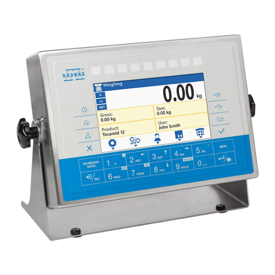
1. INTENDED USE PUE HX7 weighing indicator is a device intended to make industrial scales operating on the basis of load cells. It is equipped with a stainless steel housing of high IP. The PUE HX7 features 7’’ colour display guaranteeing perfect readability, and a diode bar graph visualising MIN, MAX thresholds. -
Page 6: Maintenance Activities
3. MAINTENANCE ACTIVITIES In order to ensure safety in the course of cleaning, it is necessary to disconnect the device from the mains. With this condition met, uninstall the weighing pan and other detachable components. Cleaning the weighing pan while still installed may cause damage of the measuring system. -
Page 7: Mechanical Design
4. MECHANICAL DESIGN 4.1. Dimensions PUE HX7 overall dimensions... -
Page 8: Connectors Arrangement
4.2. Connectors Arrangement PUE HX7 connectors Cable gland for power cord Valve USB 2 M12 4P connector (option) RS232 M12 8P connector RS232 M12 8P connector (option) RS232 M12 8P connector (option) RS485 M12 8P connector (option) Cable gland for a cable of a weighing platform 1... -
Page 9: Pins Arrangement
4.3. Pins Arrangement Pin1 – NC Pin2 – RxD Pin3 – TxD RS232 Pin4 – NC RS232 (2) Pin5 – GND RS232 (3) Pin6 - +5VDC Pin7 – GNDZ Pin8 – 24VDC Pin1 – B Pin2 – NC Pin3 – NC Pin4 –... -
Page 10: Inputs / Outputs
4.4. Inputs / Outputs Standard HX7 indicator is equipped with 4 optoisolated inputs and 4 semiconductor outputs (semiconductor relays). The signals are fed through M12 8P connectors. Pin1 – OUT1 Pin2 – OUT2 Pin3 – WY3 Pin4 – OUT4 4OUTPUTS Pin5 –... -
Page 11: I/O Schematic Diagrams
4.4.2. I/O Schematic Diagrams 4 inputs 4 outputs 4.5. Operation Panel Keys Press to switch the device on / off. Press to enter the main menu. Press to log in. Press to cancel the message. Press to zero the scale. -
Page 12: Technical Specification
Press to tare the scale. Press to change the weighing unit. Press to confirm the message. Press to confirm the weighing result (PRINT). Press to confirm the messages (ENTER). Press to cancel the message. Press to change the working mode. Programmable key assigned to an on-screen button. -
Page 13: Indicator Installation
Optional Equipment 12IN/12OUT module 12IN/12OUT cable gland AN analog output module 4 - 20 mA, 0 - 20 mA, 0 - 10 V Profibus module 2 x M12 5P connector RS485 M12 8P connector RS232 x 2 M12 8P connector 5. -
Page 14: Home Screen
The home screen features 4 sections: a top bar, a weighing result window, workspace, pictograms. Home screen view: Detailed instruction on how to configure the home screen is to be found in „PUE HX7 indicator software manual”. 6.1. Top Bar The top bar displays the following information: Working mode name and symbol. -
Page 15: Weighing Result Window
Wireless communication on. Communication with the USB flash drive on. PC keyboard connected. Printer connected. Battery charge status. Communication with a PC on. Communication with the E2R SYSTEM on. 6.2. Weighing Result Window Weighing result window provides all weighing-related data. 6.3. -
Page 16: Operating The Menu
7. OPERATING THE MENU In order to navigate the program menu use the operation panel. 7.1. Entering the Menu In order to enter the menu press key. Background colour of the first menu entry differs from the remaining ones. To navigate the program menu use the keys that operate as arrow keys. -
Page 17: Entering Numbers / Text
Press to go up the menu, or to edit parameter value and change it by one digit up. Press to select parameter group that you want to operate. The first parameter of the selected parameter group is displayed. Press to go down the menu, or to edit parameter value and change it by one digit down. - Page 18 Keys Press to enter digit 1. Press to enter digit 2. Press to enter digit 3. Press to enter digit 4. Press to enter digit 5. Press to enter „-” (minus), hold the key for a few seconds (long press). Press to enter digit 6.
-
Page 19: Text Box
7.3.2. Text Box Where: Upper-case character mode. To change keyboard working mode press key. Keyboard working mode options: - upper-case character mode, - lower- case character mode, - digit mode, - arrow keys operation, - bottom bar operation. Press to save the project to *.lb file on a USB flash drive. Press to read the project saved to *.lb file on a USB flash drive. -
Page 20: Diacritical Sign Table
Keys Press to enter . , { } : - . Press to enter a b c. Press to move the cursor to the left, long press. Press to enter d e f. Press to move the cursor up, long press. Press to enter g h i. -
Page 21: Special Sign Table
Diacritical sign table: English, German, French, Diacritical sign table: Polish. Spanish. Where: Press to activate „Caps Lock” function. Press to switch to special sign keyboard. !$& 7.3.4. Special Sign Table In order to activate special signs table while editing text box it is necessary to press and hold key. -
Page 22: Installer Instruction
8. INSTALLER INSTRUCTION The PUE HX7 indicator serves as basis of load cell scales. 8.1. Connecting 6-Wire Load Cell Connect 6-wire load cell to the main board following the diagram below: 6-wire load cell connection Load cell junction J14 Load cell signals... -
Page 23: Connecting 4-Wire Load Cell
8.2. Connecting 4-Wire Load Cell Connect 4-wire load cell to the main board following the diagram below: Connecting 4-wire load cell Load cell junction J14 Load cell signals Notes REF+ JP6 soldered REF- JP5 soldered OUTPUT+ OUTPUT- INPUT+ AGND INPUT- 8.3. -
Page 24: Factory Setup
Scale with an indicator in a Scale of compact mechanical metal housing connected design with an indicator in a with a platform via a load metal housing connected with cell signal cable. the platform via a post, etc. Platform w/o galvanic connection POINT C of the signal cable shield. -
Page 25: Global Parameters
DEFAULT VALUES DESCRIPTION Defining the device at the production Scale defining stage (refer to section 9.5). Setting scale type. For PUE HX7 value PUE HX7, PUE HX7 no metrological data is displayed, only Scale type HX7, HRP the weighing indicator name. -
Page 26: Factory Parameters
Restoring default settings (factory and Restore default user parameters). operator settings 9.3. Factory Parameters NAME DEFAULT VALUES DESCRIPTION Metrology Metrology related settings Mass divisions Display of converter divisions. Adjustment unit g, kg, lb Adjustment unit. GCOR coefficient 0.9 1.1 Gravitational correction factor. - Page 27 Stability range [d]: Predefined - Predefined, 0.1, 0.2, 0.25, 0.5, 0.6, 0.7, value taken from program- Stability range Predefined 0.8, 0.9, 1, 2, 2.5, 3, implemented tables; 0.1 10 - 4, 5, 6, 7, 8, 9, 10. value entered directly by a user. Predefined, 0, 0.2, Stability time [s]: Predefined - value 0.4, 0.6, 0.8, 1, 2, 3,...
-
Page 28: Return To Weighing
The above table presents menu structure for one platform. When more than one platform are in use, enter <Factory parameters> menu to see a list of all the platforms. Each platform is defined by an analogous set of parameters (presented above). 9.4. -
Page 29: Factory Adjustment
9.6. Factory Adjustment 9.6.1. External Adjustment Enter <Factory/Adjustment> submenu. Select <External adjustment> parameter. Message <Remove weight> is displayed. Unload the weighing pan and press key to confirm. Message <Adjustment. Please wait…> is displayed. Upon completed start mass determination... -
Page 30: Linearity Correction
9.7. Linearity Correction 9.7.1. Linearity Determination Declaring mass values for subsequent linearity steps and determining corrections using scale software. Procedure: Enter <Factory/Section linearity> submenu and select <Determine> parameter. Message <Continue?> is displayed. Press key to confirm. <Mass> edit box is displayed. ... -
Page 31: Deleting Linearity
It allows to carry out correct scale calibration/adjustment away from the point of subsequent use. The gravity correction value must be entered with reference to tables prepared by „Radwag Balances and Scales” or calculated using the below formula: Gcor ... -
Page 32: Optional Extension Modules
10. OPTIONAL EXTENSION MODULES 10.1. Additional 12IN/12OUT Module The module has been designed to expand indicator's functionality by additional 12 inputs and 12 outputs. It is equipped with optoisolated inputs and semiconductor outputs and enables free configuration of both the inputs and outputs (using indicator menu). - Page 33 10.1.2. 12IN/OUT Schematic Diagrams 12 inputs 12 outputs 10.1.3. Input / Output Signals Overview Signals transmitted via 16 x 0.5 mm cable with numbered wires. INPUTS OUTPUTS Wire number Signal Wire number Signal OUT1 OUT2 OUT3 OUT4 COMM1 COMM1 OUT5 OUT6 OUT7 OUT8...
-
Page 34: An Analog Output Module
IN10 OUT10 IN11 OUT11 IN12 OUT12 COMM3 COMM3 10.2. AN analog output module There are three different modes: AN 0 - 10 V. AN 4 - 20 mA. AN 0 - 20 mA. AN analog output module 10.2.1. -
Page 35: Additional Platform Module, Dp6
Analog output must be calibrated (adjusted); using P1 potentiometer set the correct offset (e.g. for 4 - 20mA output, adjust current so that for 0kg indication it is precisely 4mA). In case of remaining operation modes proceed analogously. 10.2.2. Technical Specifications Operation mode 4 - 20mA, 0 - 20mA, 0 - 10V Resolution... - Page 36 Load cell wiring 4 or 6 wires + shield Multi range option 10.3.2. Colours of Weighing Platform's Signal Wires Markings Marking of terminals (solder pads) Colour RADWAG on RADWAG A/D converter boards +INPUT brown -INPUT green AGND +OUTPUT yellow - OUTPUT...
-
Page 37: Profibus Module
10.4. PROFIBUS Module The PUE HX7 indicator can be equipped with PROFIBUS interface (option). This requires installation of AB6000 Anybus-IC module (Elmark Automatyka) in U1 socket of universal communication module board (385Rxxxx board, ver. Position of PROFIBUS module on 385Rxxxx board (ver.A) The indicator is equipped with input and output connectors. -
Page 38: Diagrams Of Connection Cables
11. DIAGRAMS OF CONNECTION CABLES Indicator - computer cable Indicator - printer cable (ZEBRA) Indicator - printer cable (EPSON) - Page 39 Indicator - IN/OUT cable Indicator – barcode scanner cable (LS2208) Indicator – PRINT, TARE, ZERO, STOP cable „Scale-Ethernet” cable is a standard network cable terminated with RJ45 connectors on both ends.
-
Page 40: Error Messages
12. ERROR MESSAGES...
Need help?
Do you have a question about the PUE HX7 and is the answer not in the manual?
Questions and answers