Table of Contents

Related Manuals for Avalue Technology EMS-SKLU Series


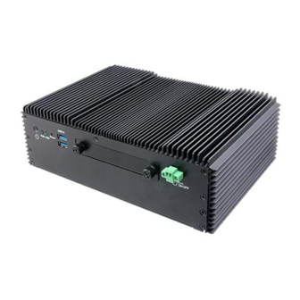
Summary of Contents for Avalue Technology EMS-SKLU Series
- Page 1 EMS-SKLU Series 6th Gen Intel® Core™ Processor i7/i5/i3/Celeron Fanless Rugged Embedded System Quick Reference Guide Ed –19 June 2020 Copyright Notice Copyright 2020 Avalue Technology Inc., ALL RIGHTS RESERVED. Part No. E2017AAG0AAR...
- Page 2 These answers are normally a lot more detailed than the ones we can give over the phone. So please consult the user’s manual first. To receive the latest version of the user’s manual; please visit our Web site at: http://www.avalue.com.tw/ 2 EMS-SKLU Series Quick Reference Guide...
-
Page 3: Table Of Contents
DB-A, EBM-CDVS DB-A and EBM-BYTS DB-E Overviews ........... 35 2.2.1 EBM-SKLUS ..........................35 2.2.2 AUX-M01 ............................ 36 2.2.3 AUX-M02 ............................ 36 2.2.4 AUX-M04 ............................ 37 2.2.5 AUX-M07 ............................ 37 2.2.6 AUX-M08 ............................ 38 2.2.7 EBM-BYTS DB-A ........................39 2.2.8 EBM-CDVS DB-A ........................39 EMS-SKLU Series Quick Reference Guide... - Page 4 Digital Output connector 1 (JDO1) ..................61 2.10.4 Digital Output connector 2 (JDO2) ..................62 2.10.5 General purpose I/O connector (DIO1) ................. 63 2.10.6 Power connector (PWR1) ...................... 64 2.10.7 Remote power button (CN1) ....................64 4 EMS-SKLU Series Quick Reference Guide...
- Page 5 3.6.2.8 Serial Port Console Redirection ..................85 3.6.2.8.1 Legacy Console Redirection Settings ................86 3.6.2.9 CPU Configuration ......................87 3.6.2.10 Intel TXT Information ......................87 3.6.2.11 SATA Configuration......................88 3.6.2.12 Network Stack Configuration ..................... 96 EMS-SKLU Series Quick Reference Guide...
- Page 6 Launch EFI Shell from filesystem device ................ 115 4. Drivers Installation ..................... 116 Install Chipset Driver ..................117 Install ME Driver ....................118 Install VGA Driver ....................119 Install Audio Driver (For Realtek ALC892) ............120 Install Ethernet Driver ..................121 6 EMS-SKLU Series Quick Reference Guide...
-
Page 7: Getting Started
Fanless Rugged Embedded System Other major components include the followings: — 44 Pin Multi I/O Cable — Wall Mount Kit — Terminal Block to Lockable DC Jack cable — DP to VGA Converter EMS-SKLU Series Quick Reference Guide... -
Page 8: System Specifications
1 x M.2, supports B-Key 2242/3042 and SIM Card slot (SSD & 3G/4G) Storage 1 x 2.5” Drive Bay Combination 1 x M.2 B-Key 2242/3042 Others support TPM2.0 (default), RAID 0/1 Front Side External I/O 8 EMS-SKLU Series Quick Reference Guide... - Page 9 Audio 1 x Mic-IN 1x Line-Out 1 x 44bit GPIO (1 x 12bit GPIO, 6-bits for input and 6-bit for output + 1 x 32bit GPIO GPIO support 1.5KV isolation.) (EMS-SKLU-GPIO) EMS-SKLU Series Quick Reference Guide...
- Page 10 1 x 3-pin DIP Switch for Power mode (AT/ATX) 1 x Buzzer 1 x 1 x 5-Pin header for 1 x USB 2.0 reservation 1 x 3-pin for EC Display Chipset Intel® Skylake Processor integrated Graphics 10 EMS-SKLU Series Quick Reference Guide...
- Page 11 Mechanical Shock With SSD : 50Grms, IEC 60068-2-27, Half Sine, 11ms Test Avalue Standard Test Criteria Drop Test [Group 1] Operating Temperature -20°C ~ 60°C (w/SSD) ambient w/ air flow EMS-SKLU Series Quick Reference Guide 11...
- Page 12 5% ~ 90% relative humidity, non-condensing Storage -40°C ~ 85°C Temperature IEC-60945 certified w/ EPM1718 Marine power board (Protected from the Other Request weather (formerly class B)) Note: Specifications are subject to change without notice. 12 EMS-SKLU Series Quick Reference Guide...
-
Page 13: System Overview
Quick Reference Guide 1.4 System Overview 1.4.1 Front View EMS-SKLU EMS-SKLU-Marine EMS-SKLU-DVI/EMS-SKLU-HDMI/EMS-SKLU-PSE/EMS-SKLU-4 COM Isolation /EMS-SKLU-6 COM/EMS-SKLU-6 LAN/EMS-SKLU-USB EMS-SKLU-GPIO EMS-SKLU Series Quick Reference Guide 13... -
Page 14: Rear View
EMS-SKLU Series 1.4.2 Rear View EMS-SKLU EMS-SKLU-Marine EMS-SKLU-DVI EMS-SKLU-HDMI 14 EMS-SKLU Series Quick Reference Guide... - Page 15 Quick Reference Guide EMS-SKLU-PSE EMS-SKLU-4 COM Isolation EMS-SKLU-6 COM EMS-SKLU-6 LAN EMS-SKLU Series Quick Reference Guide 15...
- Page 16 Power on button DP connector LAN1/2 RJ-45 Ethernet 1/2 COM1 Serial port connector 1 Multi-Function Port combined COM2, Multi-function port 2 PS/2, Audio, GPIO and SMBus DC-IN DC power-in connector EMS-SKLU-Marine Connectors Label Function Note 16 EMS-SKLU Series Quick Reference Guide...
- Page 17 Multi-Function Port combined COM2, Multi-function port 2 PS/2, Audio, GPIO and SMBus DVI-D DVI-D connector USB2.0 2 x USB2.0 connector COM1 Serial port connector 1 DP connector EMS-SKLU-HDMI Connectors Label Function Note System power indicator HDD indicator EMS-SKLU Series Quick Reference Guide 17...
- Page 18 RJ-45 Ethernet 1/2/3/4/5/6 Multi-Function Port combined COM2, Multi-function port 2 PS/2, Audio, GPIO and SMBus EMS-SKLU-4 COM Isolation Connectors Label Function Note System power indicator HDD indicator Reset Reset button USB3.0 4 x USB3.0 connector 18 EMS-SKLU Series Quick Reference Guide...
- Page 19 Connectors Label Function Note System power indicator HDD indicator Reset Reset button USB3.0 4 x USB3.0 connector Ext. ON/OFF Power on button DP connector USB2.0 2 x USB2.0 connector COM1 Serial port connector 1 EMS-SKLU Series Quick Reference Guide 19...
- Page 20 1 x USB2.0 connector DP connector COM1/2 Serial port connector 1/2 DC power-in connector DC-IN LAN1/2/3/4/5/6 RJ-45 Ethernet 1/2/3/4/5/6 Multi-Function Port combined COM2, Multi-function port 2 PS/2, Audio, GPIO and SMBus 32- bit GPIO GPIO 20 EMS-SKLU Series Quick Reference Guide...
-
Page 21: System Dimensions
Quick Reference Guide 1.5 System Dimensions 1.5.1 EMS-SKLU Front & Top view (Unit: mm) EMS-SKLU Series Quick Reference Guide 21... -
Page 22: Ems-Sklu-Marine Front & Top View
EMS-SKLU Series 1.5.2 EMS-SKLU-Marine Front & Top view (Unit: mm) 22 EMS-SKLU Series Quick Reference Guide... -
Page 23: Ems-Sklu-Dvi Front & Top View
Quick Reference Guide 1.5.3 EMS-SKLU-DVI Front & Top view (Unit: mm) EMS-SKLU Series Quick Reference Guide 23... -
Page 24: Ems-Sklu-Hdmi Front & Top View
EMS-SKLU Series 1.5.4 EMS-SKLU-HDMI Front & Top view (Unit: mm) 24 EMS-SKLU Series Quick Reference Guide... -
Page 25: Ems-Sklu-Pse Front & Top View
Quick Reference Guide 1.5.5 EMS-SKLU-PSE Front & Top view (Unit: mm) EMS-SKLU Series Quick Reference Guide 25... -
Page 26: Ems-Sklu-4 Com Isolation Front & Top View
EMS-SKLU Series 1.5.6 EMS-SKLU-4 COM Isolation Front & Top view (Unit: mm) 26 EMS-SKLU Series Quick Reference Guide... -
Page 27: Ems-Sklu-6 Com Front & Top View
Quick Reference Guide 1.5.7 EMS-SKLU-6 COM Front & Top view (Unit: mm) EMS-SKLU Series Quick Reference Guide 27... -
Page 28: Ems-Sklu-6 Lan Front & Top View
EMS-SKLU Series 1.5.8 EMS-SKLU-6 LAN Front & Top view (Unit: mm) 28 EMS-SKLU Series Quick Reference Guide... -
Page 29: Ems-Sklu-Usb Front & Top View
Quick Reference Guide 1.5.9 EMS-SKLU-USB Front & Top view (Unit: mm) EMS-SKLU Series Quick Reference Guide 29... -
Page 30: Ems-Sklu-Gpio Front & Top View
EMS-SKLU Series 1.5.10 EMS-SKLU-GPIO Front & Top view (Unit: mm) 30 EMS-SKLU Series Quick Reference Guide... -
Page 31: Hardware Configuration
For advanced information, please refer to: 1- EBM-SKLUS, AUX-M01, AUX-M02, AUX-M04, AUX-M07, AUX-M08, EBM-BYTS DB-A, EBM-CDVS DB-A, EBM-CDVS DB-B and EBM-BYTS DB-E included in this manual. Note: If you need more information, please visit our website: http://www.avalue.com.tw EMS-SKLU Series Quick Reference Guide 31... -
Page 32: Ems-Sklu Connector Mapping
2.1 EMS-SKLU connector mapping 2.1.1 Serial port connector 1 (COM1) RS-232 RS-485 RS-422 DATA1- TXD- DATA1+ TXD+ RXD+ RXD- 2.1.2 Serial port connector 3/4/5/6 (COM3/4/5/6) RS-232 RS-485 RS-422 DATA1- TXD- DATA1+ TXD+ RXD+ RXD- 32 EMS-SKLU Series Quick Reference Guide... -
Page 33: Multi-Function Port Combined Com2, 2 Ps/2, Audio, Gpio And Smbus (Multi-Function Port)
Multi-Function Port combined COM2, 2 PS/2, Audio, GPIO and SMBus (Multi-function port) Signal Signal Signal LINE1_JD 16 FRONT_JD LINE1_RIN MIC1_JD LINEOUT_R MIC_RIN LINE1_LIN LINEOUT_L MIC_LIN SMB_CLK MSCK SMB_DATA NRIB# NRTSB# MSDA NCTSB# COM2_GND KBDA NDSRB# NTXDB_485RXP VCC_PS2 NDTRB#_485RXN NDCDB#_485TXN KBCK NRXDB_485TXP EMS-SKLU Series Quick Reference Guide 33... -
Page 34: Gpio+Smbus
EMS-SKLU Series 2.1.3.1 GPIO+SMBUS Signal PIN PIN Signal SMBUS_DATA SMBUS_CLK GPI-D5 GPI-D4 GPO-D5 GPI-D3 GPO-D4 GPI-D2 GPO-D3 GPI-D1 GPO-D2 GPI-D0 GPO-D1 GPO-D0 2.1.3.2 COM2 Pin RS-232 RS-485 RS-422 DATA1- TXD- DATA1+ TXD+ RXD+ RXD- 34 EMS-SKLU Series Quick Reference Guide... -
Page 35: Ebm-Sklus, Aux-M01, Aux-M02, Aux-M04, Aux-M07, Aux-M08, Ebm-Byts
Quick Reference Guide 2.2 EBM-SKLUS, AUX-M01, AUX-M02, AUX-M04, AUX-M07, AUX-M08, EBM-BYTS DB-A, EBM-CDVS DB-A and EBM-BYTS DB-E Overviews 2.2.1 EBM-SKLUS EMS-SKLU Series Quick Reference Guide 35... -
Page 36: Aux-M01
EMS-SKLU Series 2.2.2 AUX-M01 2.2.3 AUX-M02 36 EMS-SKLU Series Quick Reference Guide... -
Page 37: Aux-M04
Quick Reference Guide 2.2.4 AUX-M04 2.2.5 AUX-M07 EMS-SKLU Series Quick Reference Guide 37... -
Page 38: Aux-M08
EMS-SKLU Series 2.2.6 AUX-M08 38 EMS-SKLU Series Quick Reference Guide... -
Page 39: Ebm-Byts Db-A
Quick Reference Guide 2.2.7 EBM-BYTS DB-A 2.2.8 EBM-CDVS DB-A EMS-SKLU Series Quick Reference Guide 39... -
Page 40: Ebm-Cdvs Db-B
EMS-SKLU Series 2.2.9 EBM-CDVS DB-B 2.2.10 EBM-BYTS DB-E 40 EMS-SKLU Series Quick Reference Guide... -
Page 41: Ebm-Sklus Jumper & Connector List
SIM card slot 1/2 SODDIM1 DDR4 SODIMM connector IET_CB1 Expansion slot JLPC1 LPC port connector 5 x 2 header, pitch 2.00 mm JSPI1 SPI connector 4 x 2 header, pitch 2.00 mm Serial ATA connector SATA1 EMS-SKLU Series Quick Reference Guide 41... - Page 42 M.2 KEY-B 2242/3042 connector DCOUT1 DC Output connector 6 x 1 wafer, pitch 2.50 mm 1 x 3 terminal block, pitch 5.08 JVIN1 DC-Input connector EC Debug connector 5 x 2 header, pitch 2.00 mm JEC_ROM1 42 EMS-SKLU Series Quick Reference Guide...
-
Page 43: Ebm-Sklus Jumpers & Connectors Settings
Multi-function select (SW1) In Serial Port 1 mode RS-232* RS-422 RS-485 In Serial Port 2 mode RS-232* RS-422 RS-485 * Default Power mode ATX* DDI1 mode(IET) DisplayPort HDMI* DDI2 mode(DP+) DisplayPort* HDMI Cable select EMS-SKLU Series Quick Reference Guide 43... -
Page 44: Com 1/2 Pin 9 Signal Select (Jri1/2)
EMS-SKLU Series 2.4.2 COM 1/2 pin 9 signal select (JRI1/2) JRI1 Ring* JRI2 +12V * Default 2.4.3 Serial port 1/2 RS-232/422/485 mode select (JCOM_SEL1/2) RS-232* JCOM_SEL1 JCOM_SEL2 RS-422/ 485 *Default 44 EMS-SKLU Series Quick Reference Guide... -
Page 45: Clear Cmos (Jcmos1)
Quick Reference Guide 2.4.4 Clear CMOS (JCMOS1) Normal* Clear CMOS *Default 2.4.5 LPC port connector (JLPC1) Signal PIN PIN Signal LPC_SERIRQ CLK_24M_PORT80 LPC_AD3 LPC_LFRAME# LPC_AD2 RST_PORT80# LPC_AD1 +3.3V LPC_AD0 EMS-SKLU Series Quick Reference Guide 45... -
Page 46: Spi Connector (Jspi1)
EMS-SKLU Series 2.4.6 SPI connector (JSPI1) Signal Signal HOLD# SPI_SI SPI_SO SPI_CLK SPI0_CS0# +3.3VSB 2.4.7 Front Panel Connector (CN5) Signal PWRBTN_TO_EC# PM_SYSRST# +5VSB PWR_LED- 46 EMS-SKLU Series Quick Reference Guide... -
Page 47: Dc Output Connector (Dcout1)
Quick Reference Guide 2.4.8 DC Output connector (DCOUT1) Signal +VIN +VIN +VIN 2.4.9 DC Input connector (JVIN1) Signal +DC_IN CHASSIS_GND EMS-SKLU Series Quick Reference Guide 47... -
Page 48: Ec Debug Connector (Jec_Rom1)
EMS-SKLU Series 2.4.10 EC Debug connector (JEC_ROM1) Signal Signal EC_SMDAT_DE EC_SMCLK_DE EC_HOLD# EC_FMOSI EC_FMISO EC_FSCK EC_FSCE# +VSPI_EC 2.4.11 On-board header for USB2.0 (USB2) Signal USB_z_PP2 USB_z_PN2 +5VSB 48 EMS-SKLU Series Quick Reference Guide... -
Page 49: Power On/Off Connector (Pwrbtn1)
Quick Reference Guide 2.4.12 Power ON/OFF connector (PWRBTN1) Signal PWRBTN#_R EMS-SKLU Series Quick Reference Guide 49... -
Page 50: Aux-M01, Aux-M02, Aux-M04, Aux-M07, Aux-M08, Ebm-Byts Db-A
3 x 2 header, pitch 2.00mm Connectors Label Function Note ZUSB1~2 USB connector 1~2 LAN2~5 LAN connector 2~5 Power connector 6 x 1 wafer, pitch 2.00mm ZPWR1 Z_JLANLED LAN ACT/LNK/SPD LED 8 x 2 wafer, pitch 2.00mm 50 EMS-SKLU Series Quick Reference Guide... - Page 51 IET Expansion slot 2.5.6 EBM-BYTS DB-A Jumpers Label Function Note OJRI3/4 COM 3/4 pin 9 signal select 3 x 2 header, pitch 2.00mm Connectors Label Function Note USB connector 1~2 OUSB1~2 LAN2~3 RJ-45 Ethernet 2~3 EMS-SKLU Series Quick Reference Guide 51...
- Page 52 6 x 1 wafer, pitch 2.50 mm DC Output connector DC-OUT1 6 x 1 wafer, pitch 2.50 mm 2.5.9 EBM-BYTS DB-E Connectors Label Function Note USB1~3 3 x USB2.0 connector USB4~7 4 x USB3.0 connector 52 EMS-SKLU Series Quick Reference Guide...
-
Page 53: Aux-M01 Jumpers & Connectors Settings
Quick Reference Guide 2.6 AUX-M01 Jumpers & Connectors settings 2.6.1 COM 3/4/5/6 pin 9 signal select (JRI3/4/5/6) Ring* JRI6 JRI5 +12V JRI4 JRI3 * Default 2.6.2 USB connector (USB3) Signal PUSBP3 PUSBN3 PV5A_USB3 EMS-SKLU Series Quick Reference Guide 53... -
Page 54: Usb Connector (Jusb3)
EMS-SKLU Series 2.6.3 USB connector (JUSB3) Signal PUSBP3 PUSBN3 PV5A_USB3 2.6.4 SMBUS of TCA9555 address setting (PJP1) Signal PIN PIN Signal MC_9555A0 MC_9555A1 MC_9555A2 54 EMS-SKLU Series Quick Reference Guide... -
Page 55: Aux-M02 Connectors Settings
Z_LAN_LED_100#_1 Z_LAN_LED_ACT_3 Z_LAN_LED_ACT_1 +3.3VSB +3.3VSB Z_LAN_LED_1000#_4 Z_LAN_LED_1000#_2 Z_LAN_LED_100#_4 Z_LAN_LED_100#_2 Z_LAN_LED_ACT_4 Z_LAN_LED_ACT_2 +3.3VSB +3.3VSB 2.7.2 Normal/Bypass mode LED (JLANMODE) Signal PIN PIN Signal Z_RC5_LAN23-STA Z_RC7_LAN45-STA Z_+VLED Z_+VLED Z_RA4_LAN23-BYP Z_RA1_LAN45-BYP Z_+VLED Z_+VLED Z_RC6_LAN23-NOR Z_RC4_LAN45-NOR Z_+VLED Z_+VLED EMS-SKLU Series Quick Reference Guide 55... -
Page 56: Aux-M04 Jumpers & Connectors Settings
EMS-SKLU Series 2.8 AUX-M04 Jumpers & Connectors settings 2.8.1 Operating Modes select (ZJP1) Normal Auto* Reset * Default 2.8.2 Power connector (ZPWR1) Signal +V12-28V +V12-28V +V12-28V 56 EMS-SKLU Series Quick Reference Guide... -
Page 57: Lan Act/Lnk/Spd Led (Z_Jlanled)
Quick Reference Guide 2.8.3 LAN ACT/LNK/SPD LED (Z_JLANLED) Signal PIN PIN Signal Z_LAN_LED_1000#_3 15 16 Z_LAN_LED_1000#_1 Z_LAN_LED_100#_3 Z_LAN_LED_100#_1 Z_LAN_LED_ACT_3 Z_LAN_LED_ACT_1 +3.3VSB +3.3VSB Z_LAN_LED_1000#_4 Z_LAN_LED_1000#_2 Z_LAN_LED_100#_4 Z_LAN_LED_100#_2 Z_LAN_LED_ACT_4 Z_LAN_LED_ACT_2 +3.3VSB +3.3VSB EMS-SKLU Series Quick Reference Guide 57... -
Page 58: Aux-M07 Connector Settings
EMS-SKLU Series 2.9 AUX-M07 Connector settings 2.9.1 SMBUS of TCA9555 address setting (SJP2) Signal PIN PIN Signal SMC_9555A0 SMC_9555A1 SMC_9555A2 58 EMS-SKLU Series Quick Reference Guide... -
Page 59: Aux-M08 Connectors Settings
AUX-M08 Connectors settings 2.10.1 Digital Input connector 1 (JDI1) Wet* Mode Digital Input Logic Level 0: Open Logic Level 1: Close to GND *Default Logic Level 0: +5V to 30V Wet* Logic Level 1: +3V Max EMS-SKLU Series Quick Reference Guide 59... -
Page 60: Digital Input Connector 2 (Jdi2)
EMS-SKLU Series 2.10.2 Digital Input connector 2 (JDI2) Wet* Mode Digital Input Logic Level 0: Open Logic Level 1: Close to GND *Default Logic Level 0: +5V to 30V Wet* Logic Level 1: +3V Max 60 EMS-SKLU Series Quick Reference Guide... -
Page 61: Digital Output Connector 1 (Jdo1)
Quick Reference Guide 2.10.3 Digital Output connector 1 (JDO1) Sink* *Default Note: Output Voltage: Max 250 mA per channel, current sink type. EMS-SKLU Series Quick Reference Guide 61... -
Page 62: Digital Output Connector 2 (Jdo2)
EMS-SKLU Series 2.10.4 Digital Output connector 2 (JDO2) Sink* *Default Note: Output Voltage: Max 250 mA per channel, current sink type. 62 EMS-SKLU Series Quick Reference Guide... -
Page 63: General Purpose I/O Connector (Dio1)
DIO_GPO0 DIO_GPI0 DIO_GPO1 DIO_GPI1 DIO_GPO2 DIO_GPI2 DIO_GPO3 DIO_GPI3 DIO_GPO4 DIO_GPI4 DIO_GPO5 DIO_GPI5 DIO_GPO6 DIO_GPI6 DIO_GPO7 DIO_GPI7 DIO_GPO8 DIO_GPI8 DIO_GPO9 DIO_GPI9 DIO_GPO10 DIO_GPI10 DIO_GPO11 DIO_GPI11 DIO_GPO12 DIO_GPI12 DIO_GPO13 DIO_GPI13 DIO_GPO14 DIO_GPI14 DIO_GPO15 DIO_GPI15 +VEXT_DO +VEXT_DI EMS-SKLU Series Quick Reference Guide 63... -
Page 64: Power Connector (Pwr1)
EMS-SKLU Series 2.10.6 Power connector (PWR1) Signal +VIN_PSE +VIN_PSE +VIN_PSE 2.10.7 Remote power button (CN1) Signal PWRBTN_TO_EC# 64 EMS-SKLU Series Quick Reference Guide... -
Page 65: Ebm-Byts Db-A Jumpers & Connectors Settings
Auto Direction RTS# Control* 485TXP external OPEN* biasing resistor 485TXN external OPEN* biasing resistor In Serial Port 2 mode Auto Direction RTS# Control* 485TXP external 9-10 OPEN* biasing resistor 485TXN external 11-12 OPEN* biasing resistor EMS-SKLU Series Quick Reference Guide 65... -
Page 66: Smbus Of Tca9555 Address Setting (Ojp1)
EMS-SKLU Series 2.11.3 SMBUS of TCA9555 address setting (OJP1) Signal PIN PIN Signal MC_9555A0 MC_9555A1 MC_9555A2 66 EMS-SKLU Series Quick Reference Guide... -
Page 67: Ebm-Cdvs Db-A Connector Settings
Quick Reference Guide 2.12 EBM-CDVS DB-A Connector settings 2.12.1 Front Panel Connector 1 (CN1) Signal SYSRST# SATA_LED# PWRSB_LED- EMS-SKLU Series Quick Reference Guide 67... -
Page 68: Ebm-Cdvs Db-B Connector Settings
EMS-SKLU Series 2.13 EBM-CDVS DB-B Connector settings 2.13.1 DC Input connector (DC-IN1) Signal +PWRIN +PWRIN +PWRIN 2.13.2 DC Output connector (DC-OUT1) Signal +PWROUT +PWROUT +PWROUT 68 EMS-SKLU Series Quick Reference Guide... -
Page 69: Installing Hard Disk & Memory, Pci Devices (Ems-Sklu)
Step 4. Insert M.2 B-Key card into designated locations and fasten with a screw to complete installation. WARNING: Please target the right pole when you are setting it. The black wire is corresponding to the negative pole and another one is positive pole. EMS-SKLU Series Quick Reference Guide 69... - Page 70 Step 3. Slide HDD into its bracket until properly seated. Step 4. Secure HDD by means of 4 screws. Step 5. Insert HDD bracket into designated locations and fasten with 2 screws to complete HDD installation. 70 EMS-SKLU Series Quick Reference Guide...
-
Page 71: Installing Mounting Brackets (Ems-Sklu)
2.15 Installing Mounting Brackets (EMS-SKLU) Step 1. Position brackets on rear sides, matching the holes on the system. Step 2. Insert and fasten screw on each side of the system to secure Mounting brackets. EMS-SKLU Series Quick Reference Guide 71... -
Page 72: Installing Hard Disk (Ems-Sklu-Gpio)
Step 2. Remove 4 screws from the board and take it off. Step 3. Secure HDD by means of 4 screws. Step 4. Insert HDD bracket into designated locations and fasten with 4 screws to complete HDD installation. 72 EMS-SKLU Series Quick Reference Guide... -
Page 73: Bios Setup
Quick Reference Guide 3.BIOS Setup EMS-SKLU Series Quick Reference Guide 73... -
Page 74: Introduction
If you do not press the keys at the correct time and the system does not boot, an error message will be displayed and you will again be asked to. Press F1 to Continue, DEL to enter SETUP 74 EMS-SKLU Series Quick Reference Guide... -
Page 75: Using Setup
Note: Some of the navigation keys differ from one screen to another. To Display a Sub Menu Use the arrow keys to move the cursor to the sub menu you want. Then press <Enter>. A “” pointer marks all sub menus. EMS-SKLU Series Quick Reference Guide 75... -
Page 76: Getting Help
BIOS Vendor and your systems manufacturer to provide the absolute maximum performance and reliability. Even a seemingly small change to the chipset setup has the potential for causing you to use the override. 76 EMS-SKLU Series Quick Reference Guide... -
Page 77: Bios Setup
<Enter> to accept and enter the sub-menu. 3.6.1 Main Menu This section allows you to record some basic hardware configurations in your computer and set the system clock. EMS-SKLU Series Quick Reference Guide 77... -
Page 78: System Language
Visit the Avalue website (www.avalue.com.tw) to download the latest product and BIOS information. 3.6.2 Advanced Menu This section allows you to configure your CPU and other system devices for basic operation through the following sub-menus. 78 EMS-SKLU Series Quick Reference Guide... -
Page 79: Trusted Computing
Enabled[Default], Disabled Enable or Disable Endorsement Endorsement Hierarchy Enabled[Default], Hierarchy. Select the TCG2 Spec Version Support. 1.0[Default], 1.0: the Compatible mode for TPM2.0 UEFI Spec Version Win8/Win10, 1.x: For TCG2 newer spec for Win10. EMS-SKLU Series Quick Reference Guide 79... -
Page 80: Acpi Settings
ErP Function ErP Function (Deep S5). Enabled Off[Default] PWR-On After PWR-Fail AC loss resume. Last state Disabled[Default], 30 sec 40 sec 50 sec Watch Dog Select WatchDog. 1 min 2 min 10 min 30 min 80 EMS-SKLU Series Quick Reference Guide... -
Page 81: Amt Configuration
Extension. Note: iAMT H/W is always enabled. This option Intel AMT Enabled[Default], just controls the BIOS extension execution. If enabled, this requires additional firmware in the SPI device. Disabled[Default] Un-Configure ME OEMFlag Bit 15: Un-Configure ME without password. Enabled, EMS-SKLU Series Quick Reference Guide 81... -
Page 82: Pch-Fw Configuration
Select the desired fTPM solution to be fTPM Switch Selection MSFT QFE Solution used. 3.6.2.4.1 Firmware Update Configuration Item Option Description Disabled [Default], ME FW Image Re-Flash Enable/Disable Me FW Image Re-Flash function. Enabled 82 EMS-SKLU Series Quick Reference Guide... -
Page 83: It8528 Super Io Configuration
Please refer to 3.6.2.5.1~ 3.6.2.5.2 for more information. Item Description Serial Port 1 Configuration Set Parameters of Serial Port 1 (COMA). Serial Port 2 Configuration Set Parameters of Serial Port 2 (COMB). 3.6.2.5.1 Serial Port 1 Configuration EMS-SKLU Series Quick Reference Guide 83... -
Page 84: Serial Port 2 Configuration
Description Enabled[Default], Serial Port Enable or Disable Serial Port (COM). Disabled 3.6.2.5.2 Serial Port 2 Configuration Item Option Description Enabled[Default], Serial Port Enable or Disable Serial Port (COM). Disabled 3.6.2.6 EC 8528 H/W Monitor 84 EMS-SKLU Series Quick Reference Guide... -
Page 85: S5 Rtc Wake Settings
Fixed Time, system will wake on the hr::min::sec Wake system from S5 Fixed Time specified. Select Dynamic Time, System will wake on Dynamic Time the current time + Increase minute(s). 3.6.2.8 Serial Port Console Redirection EMS-SKLU Series Quick Reference Guide 85... -
Page 86: Legacy Console Redirection Settings
Console Redirection Console Redirection Enable or Disable. Enabled 3.6.2.8.1 Legacy Console Redirection Settings Item Option Description Select a COM port to display redirection of Legacy Serial Redirection Port COM1[Default], Legacy OS and Legacy OPROM Messages. 86 EMS-SKLU Series Quick Reference Guide... -
Page 87: Cpu Configuration
Quick Reference Guide 3.6.2.9 CPU Configuration Use the CPU configuration menu to view detailed CPU specification and configure the CPU. 3.6.2.10 Intel TXT Information EMS-SKLU Series Quick Reference Guide 87... -
Page 88: Sata Configuration
Enabled[Default] Port 1/2 Enable or Disable SATA Port. Disabled, Hard Disk Drive [Default] Identify the SATA port is connected to Solid SATA Device Type Solid State Drive State Drive or Hard Disk Drive. 88 EMS-SKLU Series Quick Reference Guide... - Page 89 To set RAID configuration, please follow the instruction below. Set RAID 0 (DATA Striping) Step 1: Select “Advanced” Page Select “SATA Configuration” Item Select “SATA mode selection” Item as “RAID” Save and Reset System EMS-SKLU Series Quick Reference Guide 89...
- Page 90 EMS-SKLU Series Step 2: Enter “Intel® Rapid Storage Technology” Select “Advanced” Page Select “Intel® Rapid Storage Technology Step 3: Enter “Create RAID Volume” Select “Create RAID Volume 90 EMS-SKLU Series Quick Reference Guide...
- Page 91 Step 4: Enter “Name “as “name of raid “and Set “RAID Level” as “RAID0” Enter “Name” item as “name of raid” Select “RAID Level” item as “RAID0” Step 5: Select disk SATA 0.1 and SATA 0.2 Select “Strip Size” Select “Capacity” Enter “Create Volume” EMS-SKLU Series Quick Reference Guide 91...
- Page 92 EMS-SKLU Series Step 6: Completed. This page show the information of raid created by user Delete Raid 0: Step1: Enter “Delete” 92 EMS-SKLU Series Quick Reference Guide...
- Page 93 Quick Reference Guide Step 2: Select “Yes “to delete RAID Set RAID 1 (DATA Mirroring) Step1: Enter “Create RAID Volume” EMS-SKLU Series Quick Reference Guide 93...
- Page 94 - Set “RAID Level “ as “RAID1” - Select disk “SATA 0.1” and ”SATA 0.2” - Select “Strip Size” - Select “Capacity” - Enter “Create Volume” Step 3: Raid 1 be created. Select”Volume1” to see detail. 94 EMS-SKLU Series Quick Reference Guide...
- Page 95 Quick Reference Guide Step 4: Completed. This page show the information of raid created by user. Delete Raid 1 Step1: Enter “Delete” EMS-SKLU Series Quick Reference Guide 95...
-
Page 96: Network Stack Configuration
EMS-SKLU Series Step2: Select “Yes” to delete RAID 3.6.2.12 Network Stack Configuration Item Options Description Enabled Network Stack Enable/Disable UEFI Network Stack. Disabled[Default], 96 EMS-SKLU Series Quick Reference Guide... -
Page 97: Csm Configuration
Quick Reference Guide 3.6.2.13 CSM Configuration Item Options Description Enabled CSM Support Enable/Disable CSM Support. Disabled[Default] 3.6.2.14 USB Configuration The USB Configuration menu helps read USB information and configures USB settings. EMS-SKLU Series Quick Reference Guide 97... - Page 98 Floppy enumerates devices according to their media Hp v220w 1100 Forced FDD format. Optical drives are emulated as ‘CDROM’, drives with no media will be Hard Disk CD-ROM emulated according to d drive type. 98 EMS-SKLU Series Quick Reference Guide...
-
Page 99: Chipset
Quick Reference Guide 3.6.3 Chipset 3.6.3.1 System Agent (SA) Configuration Item Option Description Enabled[Default] VT-d VT-d capability. Disabled EMS-SKLU Series Quick Reference Guide 99... -
Page 100: Graphics Configuration
3.6.3.1.1 Graphics Configuration 3.6.3.1.2 Memory Configuration Item Option Description Dynamic[Default] Maximum Value of TOLUD. Dynamic 1GB/1.25GB/1.5GB/1.75GB assignment would adjust TOLUD Max TOLUD /2GB/2.25GB/2.5GB/2.75GB automatically based on largest MMIO length /3GB/3.25GB of installed graphic controller. 100 EMS-SKLU Series Quick Reference Guide... -
Page 101: Pch-Io Configuration
PCH-IO Configuration Item Option Description Disabled PCH LAN Controller Enable or disable onboard NIC. Enabled[Default] Disabled[Default] Enable/Disable LAN Phy driving LAN_WAKE# LAN PHY Drives LAN_WAKE# Enabled else platform drives LAN_WAKE#. 3.6.3.2.1 PCI Express Configuration EMS-SKLU Series Quick Reference Guide 101... -
Page 102: Pci Express Root Port2 (Mpcie)
L0s State AUTO – BIOS auto ASPM Support configure DISABLE – Disables ASPM. L0sL1 Auto Disabled L1.1 L1 Substates PCI Express L1 Substates settings. L1.2 L1.1 & L1.2[Default], Auto[Default] Gen1 PCIe Speed Select PCI Express port speed. Gen2 Gen3 102 EMS-SKLU Series Quick Reference Guide... -
Page 103: Pci Express Root Port3 (I210/211)
L0s State AUTO – BIOS auto ASPM Support configure DISABLE – Disables ASPM. L0sL1 Auto Disabled L1.1 L1 Substates PCI Express L1 Substates settings. L1.2 L1.1 & L1.2[Default], Auto[Default] Gen1 PCIe Speed Select PCI Express port speed. Gen2 Gen3 EMS-SKLU Series Quick Reference Guide 103... -
Page 104: Pci Express Root Port5 (Iet)
L0s State AUTO – BIOS auto ASPM Support configure DISABLE – Disables ASPM. L0sL1 Auto Disabled L1.1 L1 Substates PCI Express L1 Substates settings. L1.2 L1.1 & L1.2[Default], Auto[Default] Gen1 PCIe Speed Select PCI Express port speed. Gen2 Gen3 104 EMS-SKLU Series Quick Reference Guide... -
Page 105: Pci Express Root Port6 (Iet)
L0s State AUTO – BIOS auto ASPM Support configure DISABLE – Disables ASPM. L0sL1 Auto Disabled L1.1 L1 Substates PCI Express L1 Substates settings. L1.2 L1.1 & L1.2[Default], Auto[Default] Gen1 PCIe Speed Select PCI Express port speed. Gen2 Gen3 EMS-SKLU Series Quick Reference Guide 105... -
Page 106: Pci Express Root Port7 (Iet)
L0s State AUTO – BIOS auto ASPM Support configure DISABLE – Disables ASPM. L0sL1 Auto Disabled L1.1 L1 Substates PCI Express L1 Substates settings. L1.2 L1.1 & L1.2[Default], Auto[Default] Gen1 PCIe Speed Select PCI Express port speed. Gen2 Gen3 106 EMS-SKLU Series Quick Reference Guide... -
Page 107: Pci Express Root Port8 (Iet)
L0s State AUTO – BIOS auto ASPM Support configure DISABLE – Disables ASPM. L0sL1 Auto Disabled L1.1 L1 Substates PCI Express L1 Substates settings. L1.2 L1.1 & L1.2[Default], Auto[Default] Gen1 PCIe Speed Select PCI Express port speed. Gen2 Gen3 EMS-SKLU Series Quick Reference Guide 107... -
Page 108: Pci Express Root Port12 (M.2)
L0s State AUTO – BIOS auto ASPM Support configure DISABLE – Disables ASPM. L0sL1 Auto Disabled L1.1 L1 Substates PCI Express L1 Substates settings. L1.2 L1.1 & L1.2[Default], Auto[Default] Gen1 PCIe Speed Select PCI Express port speed. Gen2 Gen3 108 EMS-SKLU Series Quick Reference Guide... -
Page 109: Usb Configuration
Option to disable Compliance Mode. Default FALSE[Default], XHCI Disable Compliance Mode is FALSE to not disable Compliance Mode. TRUE Set TRUE to disable Compliance Mode. Disabled[Default] USB SS Physical Connector #2(M.2) Enable/Disable USB port. Enabled EMS-SKLU Series Quick Reference Guide 109... -
Page 110: Hd Audio Configuration
Control Detection of the HD-Audio device. Disable = HDA will Disabled be unconditionally disabled Enabled = HDA will be HD Audio Enabled unconditionally enabled Auto = HDA will be enabled if Auto[Default], present, disabled otherwise. 3.6.4 Security 110 EMS-SKLU Series Quick Reference Guide... -
Page 111: Secure Boot Menu
User mode with enrolled Platform Key(PK) Enabled 2.CSM function is disabled. Secure Boot mode selector. ‘Custom’ Mode Standard Secure Boot Mode enables users to change Image Execution policy Custom[Default] and manage Secure Boot Keys. EMS-SKLU Series Quick Reference Guide 111... -
Page 112: Key Management
EMS-SKLU Series 3.6.4.1.1 Key Management Item Option Description Enabled, Install factory default Secure Boot Keys Provision Factory Default keys Disabled[Default] when System is in Setup Mode. 112 EMS-SKLU Series Quick Reference Guide... -
Page 113: Boot
Enables or disables boot with initialization of a Disabled[Default] minimal set of devices required to launch Fast Boot Enabled active boot option. Has no effect for BBS boot options. Boot Option #1/2 Set the system boot order. EMS-SKLU Series Quick Reference Guide 113... -
Page 114: Save And Exit
EMS-SKLU Series 3.6.6 Save and exit 3.6.6.1 Save Changes and Reset Reset the system after saving the changes. 114 EMS-SKLU Series Quick Reference Guide... -
Page 115: Discard Changes And Reset
This option restores all BIOS settings to the factory default. This option is useful if the controller exhibits unpredictable behavior due to an incorrect or inappropriate BIOS setting. 3.6.6.4 Launch EFI Shell from filesystem device Attempts to Launch EFI Shell application (Shellx64.efi) from one of the available filesystem devices. EMS-SKLU Series Quick Reference Guide 115... -
Page 116: Drivers Installation
EMS-SKLU Series 4. Drivers Installation Note: Installation procedures and screen shots in this section are for your reference and may not be exactly the same as shown on your screen. 116 EMS-SKLU Series Quick Reference Guide... -
Page 117: Install Chipset Driver
If the warning message appears while the installation process, click Continue to go on. Step 3. Click Install. Step1. Click Next. Step 4. Click Restart Now/Restart Later to complete setup. Step 2. Click Accept. EMS-SKLU Series Quick Reference Guide 117... -
Page 118: Install Me Driver
Continue to go on. Step 3. Click Next to proceed setup. Step1. Click Next to start installation. Step 4. Click Finish to complete setup. Step 2. Click Next. 118 EMS-SKLU Series Quick Reference Guide... -
Page 119: Install Vga Driver
Windows 10 operation system. Step 3. Click Next. Step 1. Click Next to continue installation. Step 4. Click Next. Step 2. Step 5. Click Finish to complete setup. Click Yes to accept license agreement. EMS-SKLU Series Quick Reference Guide 119... -
Page 120: Install Audio Driver (For Realtek Alc892)
Website: http://www.avalue.com.tw. Note: The installation procedures and screen shots in this section are based on Windows 10 operation system. Step 1. Click Next to continue setup. Step 2. Click Finish to complete the setup. 120 EMS-SKLU Series Quick Reference Guide... -
Page 121: Install Ethernet Driver
Windows 10 operation system. Step 3. Click Next. Step 4. Click Next. Step 1. Click Install Drivers and Software. Step 5. Click Install. Step 2. Click Next. EMS-SKLU Series Quick Reference Guide 121... - Page 122 EMS-SKLU Series Step 6. Click Finish to complete the setup. 122 EMS-SKLU Series Quick Reference Guide...
Need help?
Do you have a question about the EMS-SKLU Series and is the answer not in the manual?
Questions and answers