Table of Contents

Related Manuals for Avalue Technology ERS-CDVE


Summary of Contents for Avalue Technology ERS-CDVE
- Page 1 ERS-CDVE Fanless Intel® Atom™ D2550 Rugged Embedded System with Intel® NM10 Express Chipset Quick Reference Guide Ed –25 July 2013 Copyright Notice Copyright 2013 Avalue Technology Inc., ALL RIGHTS RESERVED. Part No. E2017ERSEA1R...
- Page 2 Disclaimer Avalue Technology Inc. reserves the right to make changes, without notice, to any product, including circuits and/or software described or contained in this manual in order to improve design and/or performance. Avalue Technology assumes no responsibility or liability for the...
-
Page 3: Table Of Contents
Front & Top View ......................... 8 1.4.2 Front View ............................ 9 1.4.3 Rear View ............................. 9 Hardware Configuration ................... 11 ERS-CDVE connector mapping................12 2.1.1 External Serial Port 1/3/4/5/6/7/8/9/10 connector (COM1/3/4/5/6/7/8/9/10) ......12 2.1.2 VGA connector (VGA) ........................ 12 2.1.3 LPT connector (LPT Port) ...................... - Page 4 ERS-CDVE 2.6.1 System reset (WCN1) ........................ 26 2.6.2 LPT Port (WJPRT1) ........................26 Installing Mounting Brackets (ERS-CDVE) ............27 Installing Hard Disk & Memory, PCI devices (ERS-CDVE) ......... 28 4 ERS-CDVE Quick Reference Guide...
-
Page 5: Getting Started
Place all electronic components in a static-dissipative surface or static-shielded bag when they are not in the chassis. 1.2 Packing List 1 x ERS-CDVE Fanless Intel® Atom™ D2550 Rugged Embedded System with Intel® NM10 Express Chipset 1 x Quick Reference Guide ... -
Page 6: System Specifications
1 x Dual-channel 18/ 24-bit LVDS Display Chipset Intel® Cedarview Integrated Graphics Resolution CRT Mode: 1920 x 1200 @ 60Hz Audio Audio Chipset Realtek ALC892 Supports 5.1-CH Audio Audio Interface Line-in, Line-out and Mic-in 6 ERS-CDVE Quick Reference Guide... - Page 7 10 ~ 500Hz, 1hr/axis Shock Protection With mSATA/ SSD: 50G, IEC 60068-2-27, Half Sine,11ms Certification CE, FCC Class B Dimension (W x D x H) 231mm x 160mm x 80mm Weight 7.7lbs (3.5Kgs) ERS-CDVE Quick Reference Guide...
-
Page 8: System Overview
ERS-CDVE 1.4 System Overview 1.4.1 Front & Top View 8 ERS-CDVE Quick Reference Guide... -
Page 9: Front View
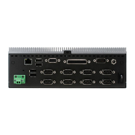
Quick Reference Guide 1.4.2 Front View 1.4.3 Rear View ERS-CDVE Quick Reference Guide... - Page 10 Multi-Function Port combined COM2, 44-pin Multi-function 2 PS/2, Audio, GPIO and SMBus USB connector VGA connector 2.5” Driver Bay and SIM Card Swappable Drawer LPT Port LPT connector LVDS Port LVDS connector Power Switch Power-in connector 10 ERS-CDVE Quick Reference Guide...
-
Page 11: Hardware Configuration
2. Hardware Configuration Jumper and Connector Setting, Driver and BIOS Installing For advanced information, please refer to: 1- EBM-CDVS and AUX-M03 included in this manual. Note: If you need more information, please visit our website: http://www.avalue.com.tw ERS-CDVE Quick Reference Guide 11... -
Page 12: Ers-Cdve Connector Mapping
2.1 ERS-CDVE connector mapping 2.1.1 External Serial Port 1/3/4/5/6/7/8/9/10 connector (COM1/3/4/5/6/7/8/9/10) Signal PIN PIN Signal NDCDA#_485TXN NDSRA# NRXDA#_485TXP NRTSA# NTXDA#_485RXP NCTSA# NDTRA#_485RXN NRIA# 2.1.2 VGA connector (VGA) Signal PIN Signal PIN Signal GREEN SDT_DDC BLUE VGA_HS VGA_VS SCK_DDC 12 ERS-CDVE Quick Reference Guide... -
Page 13: Lpt Connector (Lpt Port)
LPT_INIT# LPT_SLIN# LPT_ACK# LPT_BUSY LPT_PE LPT_SLCT 2.1.4 LVDS connector (LVDS Port) Signal Signal Signal 3.3V LVDS_DATA2_P 3.3V LVDS_DATA2_N LVDS_DDC_DATA LVDS_DATA3_P LVDS_CLKP LVDS_DDC_CLK LVDS_DATA3_N LVDS_CLKN LVDS_DATA0_P LVDS_DATA3_P LVDS_DATA0_N LVDS_DATA3_N LVDS_DATA1_P BKL1_5V LVDS_DATA1_N BKL1_Bright BKL1_BKLTEN BKL1_GND BKL1_12V ERS-CDVE Quick Reference Guide 13... -
Page 14: Multi-Function Port Combined Com2, 2 Ps/2, Audio, Gpio And Smbus (Multi-Function Port)
Multi-Function Port combined COM2, 2 PS/2, Audio, GPIO and SMBus (Multi-function port) Signal Signal Signal LINE1_JD FRONT_JD LINE1_RIN MIC1_JD LINEOUT_R MIC_RIN LINE1_LIN LINEOUT_L MIC_LIN SMB_CLK MSCK SMB_DATA NRIB# NRTSB# MSDA NCTSB# COM2_GND KBDA NDSRB# NTXDB_485RXP VCC_PS2 29 NDTRB#_485RXN NDCDB#_485TXN KBCK NRXDB_485TXP 14 ERS-CDVE Quick Reference Guide... -
Page 15: Gpio+Smbus
Quick Reference Guide 2.1.4.1 GPIO+SMBUS Signal PIN PIN Signal SMBUS_DATA SMBUS_CLK GPI-D5 GPI-D4 GPO-D5 GPI-D3 GPO-D4 GPI-D2 GPO-D3 GPI-D1 GPO-D2 GPI-D0 GPO-D1 GPO-D0 2.1.4.2 COM2 Signal PIN PIN Signal ERS-CDVE Quick Reference Guide 15... -
Page 16: Ebm-Cdvs And Aux-M03 Overviews
ERS-CDVE 2.2 EBM-CDVS and AUX-M03 Overviews 2.2.1 EBM-CDVS 16 ERS-CDVE Quick Reference Guide... - Page 17 Quick Reference Guide ERS-CDVE Quick Reference Guide 17...
-
Page 18: Aux-M03
USB connector LAN1 LAN connector CRT1 VGA connector 1. COM2 2. Audio(line-in, line-out, DB-44 Multi-function port mic-in) 3. 2 x PS/2 for KB/MS, 4. 12 bit GPIO/SMBUS COM1 Serial port connector 1 DCJACK DC-IN connector 18 ERS-CDVE Quick Reference Guide... -
Page 19: Aux-M03 Connector List
WUSB_REAR USB connector Serial port connector 3 & 7 COM3_7 COM4_8 Serial port connector 4 & 8 COM5_9 Serial port connector 5 & 9 COM6_10 Serial port connector 6 & 10 WMIOE_IO IET Expansion slot ERS-CDVE Quick Reference Guide 19... -
Page 20: Ebm-Cdvs Jumpers & Connectors Settings
ERS-CDVE 2.5 EBM-CDVS Jumpers & Connectors settings 2.5.1 Clear CMOS (CMOS1) Protect* Clear CMOS *Default 2.5.2 COM 1/2 pin 9 signal select (JRI1/2) Ring* +12V JRI1 JRI2 * Default 20 ERS-CDVE Quick Reference Guide... -
Page 21: Lpc Port Connector (Lpc1)
Quick Reference Guide 2.5.3 LPC port connector (LPC1) Signal Signal LPC_AD0 LPC_AD1 PLTRST# LPC_AD2 LPC_LFRAME# LPC_AD3 LPC1_PCI_CLK SERIRQ LPC_LDRQ1# 2.5.4 Power connector (PWR1) Signal +12V ERS-CDVE Quick Reference Guide 21... -
Page 22: Lcd Inverter Connector (Bkl1)
ERS-CDVE 2.5.5 LCD inverter connector (BKL1) Signal +12V LVDS_BKLTEN BRIGHT 2.5.6 LCD backlight brightness adjustment (JVR) Signal BRIGHT Variation Resistor (Recommended: 4.7KΩ, >1/16W) 22 ERS-CDVE Quick Reference Guide... -
Page 23: Spi Connector (Spi1)
Quick Reference Guide 2.5.7 SPI connector (SPI1) Signal Signal SPI_CS# SPI_CLK SPI_SO SPI_SI SPI_HOLD# 2.5.8 Front Panel Connector 1 (CN1) Signal PWRBTN# RESET# POWER LED+ POWER LED- ERS-CDVE Quick Reference Guide 23... -
Page 24: Front Panel Connector 2 (Cn2)
ERS-CDVE 2.5.9 Front Panel Connector 2 (CN2) Signal SATA_LED+ SATA_LED- LAN ACT LED+ LAN ACT LED- LAN LINK100+ LAN LINK100- LAN LINK1000+ LAN LINK1000- 2.5.10 DC Output connector (DCOUT_S) Signal DCIN DCIN DCIN 24 ERS-CDVE Quick Reference Guide... -
Page 25: At/Atx Mode Selector (Sw1)
AT mode This Mode supports AT power supply, no need to press Power button to enable power on/off ATX mode This Mode supports ATX power supply. Press the ATX power button to enable power on/off ERS-CDVE Quick Reference Guide 25... -
Page 26: Aux-M03 Connectors Settings
ERS-CDVE 2.6 AUX-M03 Connectors settings 2.6.1 System reset (WCN1) Signal WSYSRST# 2.6.2 LPT Port (WJPRT1) Signal Signal LPT_SLCT LPT_[E LPT_BUSY LPT_ACK# LPT_SLIN# LPT_INIT# LPT_ERR# LPT_AFD# STB- 26 ERS-CDVE Quick Reference Guide... -
Page 27: Installing Mounting Brackets (Ers-Cdve)
Quick Reference Guide 2.7 Installing Mounting Brackets (ERS-CDVE) Step 1. Locate brackets on both sides, matching the holes on the system. Step 2. Insert and fasten 3 screws on each side of the system to secure Mounting brackets. ERS-CDVE Quick Reference Guide 27... -
Page 28: Installing Hard Disk & Memory, Pci Devices (Ers-Cdve)
ERS-CDVE 2.8 Installing Hard Disk & Memory, PCI devices (ERS-CDVE) Step 1. Remove 4 screws to release the HDD bracket. Step 2.1. Slide HDD into its bracket until properly seated. Step 2.2. Secure HDD by means of 4 screws. Step 3. Remove 3 screws on each side of the system to release Mounting brackets and chassis cover.
Need help?
Do you have a question about the ERS-CDVE and is the answer not in the manual?
Questions and answers