Table of Contents

Related Manuals for Avalue Technology E640


Summary of Contents for Avalue Technology E640
- Page 1 EPC-QB Fanless Intel® Atom™ E640 Tiny Box PC with Intel® Platform Controller Hub EG20T Chipset Quick Reference Guide Ed – 4 June 2012 Copyright Notice Copyright 2012 Avalue Technology Inc., ALL RIGHTS RESERVED. Part No. E2017EPCQA0R...
- Page 2 EPC-QB FCC Statement THIS DEVICE COMPLIES WITH PART 15 FCC RULES. OPERATION IS SUBJECT TO THE FOLLOWING TWO CONDITIONS: (1) THIS DEVICE MAY NOT CAUSE HARMFUL INTERFERENCE. (2) THIS DEVICE MUST ACCEPT ANY INTERFERENCE RECEIVED INCLUDING INTERFERENCE THAT MAY CAUSE UNDESIRED OPERATION. THIS EQUIPMENT HAS BEEN TESTED AND FOUND TO COMPLY WITH THE LIMITS FOR A CLASS "A"...
- Page 3 Please do not hesitate to call or e-mail Headquarters and Branch Avalue USA Avalue Technology Inc. Avalue Technology Inc. 7F, 228, Lian-cheng Road, Chung Ho City, Taipei, 9 Timber Lane, Marlboro, NJ 07746-1443...
-
Page 4: Table Of Contents
EPC-QB Content Getting Started ......................5 Safety Precautions ....................5 Packing List ......................5 System Specifications ................... 6 System Overview ....................8 1.4.1 Front View ............................ 8 1.4.2 Rear View ............................. 9 System Dimensions ..................... 10 1.5.1 Top /Front& Side view ........................ 10 1.5.2 Bottom view.......................... -
Page 5: Getting Started
1.2 Packing List Before you begin installing your single board, please make sure that the following materials have been shipped: 1 x EPC-QB Fanless Intel® Atom™ E640 Tiny Box PC with Intel® Platform Controller Hub EG20T Chipset 1 x Quick Reference Guide ... -
Page 6: System Specifications
EPC-QB 1.3 System Specifications System Board ECM-QB Onboard Intel® Atom™ E640 1.00GHz CPU AMI 16Mbit Flash BIOS BIOS Intel® Platform Controller Hub EG20T Chipset System Chipset Nuvoton W83627DHG-P I/O Chip System Memory Onboard DDR2 1GB Memory 1 x CompactFlash Type I/II Socket, 1 x MicroSD 1 x 2.5”... - Page 7 Quick Reference Guide With CF/ SSD: 1.5Grms, IEC 60068-2-64, Random, Vibration Protection 5 ~ 500Hz, 30min/axis Shock Protection With CF/ SSD: 10G, IEC 60068-2-27, Half Sine,11ms 7” x 5.6” x 2.0” (178mm x 142mm x 50mm) Dimension (W x D x H) Weight 2.7lbs (1.2Kgs) Mounting...
-
Page 8: System Overview
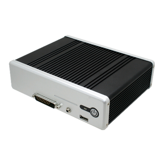
EPC-QB 1.4 System Overview 1.4.1 Front View Connectors Label Function Note POWER Power on button System power indicator USB 2.0 connector LINE OUT Line-out audio jack GPIO 8 IN/8 OUT General purpose I/O connector 8 EPC-QB Quick Reference Guide... -
Page 9: Rear View
Quick Reference Guide 1.4.2 Rear View Connectors Label Function Note COM1 Serial port 1 connector DB-9 male connector COM2 Serial port 2 connector DB-9 male connector HDD indicator Compact Flash CF card connector POWER 12V DC POWER connector LAN1&2 2 x 10/100Base-Tx Ethernet connector RJ-45 RS-422/485/CAN Serial port 5 in RS-485 mode/ Serial port 4 in RS-422 mode / CAN connector... -
Page 10: System Dimensions
EPC-QB 1.5 System Dimensions 1.5.1 Top /Front& Side view (Unit: mm) 1.5.2 Bottom view (Unit: mm) 10 EPC-QB Quick Reference Guide... -
Page 11: Hardware Configuration
Quick Reference Guide 2. Hardware Configuration Jumper and Connector Setting, Driver and BIOS Installing Please refer to ECM-QB Quick Installation Guide or User’s Manual for advanced information. Note: If you need more information, please visit our website: http://www.avalue.com.tw EPC-QB Quick Reference Guide 11... -
Page 12: Epc-Qb Connector List
EPC-QB 2.1 EPC-QB connector list Connectors Label Function Note POWER Power on button System power indicator USB 2.0 connector LINE OUT Line-out audio jack GPIO 8 IN/8 OUT General purpose I/O connector COM1 Serial port 1 connector DB-9 male connector COM2 Serial port 2 connector DB-9 male connector... -
Page 13: Epc-Qb Connector Mapping
Quick Reference Guide 2.2 EPC-QB connector mapping 2.2.1 Serial port 1 connector (COM1) Signal Signal DCD#1 RxD1 TxD1 DTR#1 DSR#1 RTS#1 CTS#1 RI#1 2.2.2 Serial port 2 connector (COM2) Signal PIN PIN Signal DCD#2 RxD2 TxD2 DTR#2 DSR#2 RTS#2 CTS#2 RI#2 EPC-QB Quick Reference Guide 13... -
Page 14: Serial Port 5 In Rs-485 Mode/ Serial Port 4 In Rs-422 Mode
EPC-QB 2.2.3 Serial port 5 in RS-485 mode/ Serial port 4 in RS-422 mode / CAN connector (RS-422/485/CAN) Signal PIN PIN Signal 485 Data+ 485 Data- 422 RxD+ 422 RxD+ CAN bus+ CAN bus- 422 TxD+ 422 TxD- 2.2.4 General purpose I/O connector (GPIO 8 IN/8 OUT) Signal PIN PIN Signal... -
Page 15: Installing Hard Disk & Memory
Quick Reference Guide 2.3 Installing Hard Disk & Memory Step 1. Remove 8 screws from two sides, 4 screws from COM and VGA as displayed above, before you can remove the chassis cover. Step 2. Detach front & rear chassis, then remove 4 screws from the bottom side Step 3. - Page 16 EPC-QB Step 4. Re-place the bottom cover, fasten with 4 screws to lock, then re-assemble the front/rear chassis Step 5. Return & fasten 8 screws back to complete installation. 16 EPC-QB Quick Reference Guide...
Need help?
Do you have a question about the E640 and is the answer not in the manual?
Questions and answers