
Related Manuals for Avalue Technology EPC-BSW


Summary of Contents for Avalue Technology EPC-BSW
- Page 1 EPC-BSW Fanless Intel® Celeron® SoC Tiny Box PC Quick Reference Guide Ed – 03 February 2016 Copyright Notice Copyright 2016 Avalue Technology Inc., ALL RIGHTS RESERVED. Part No. E2017CAH0A0R...
- Page 2 These answers are normally a lot more detailed than the ones we can give over the phone. So please consult the user’s manual first. To receive the latest version of the user’s manual; please visit our Web site at: http://www.avalue.com.tw/ 2 EPC-BSW Quick Reference Guide...
-
Page 3: Table Of Contents
Serial Port 2/3/4/5 connector (COM2/3/4/5) ................11 AUX-032 User’s Guide ..................12 2.2.1 Jumper and Connector Layout....................12 2.2.2 Jumper and Connector List ......................12 2.2.3 Setting Jumper and Connector ....................13 Installing Hard Disk & Memory (EPC-BSW) ............14 EPC-BSW Quick Reference Guide... -
Page 4: Getting Started
Place all electronic components in a static-dissipative surface or static-shielded bag when they are not in the chassis. 1.2 Packing List 1 x EPC-BSW Fanless Intel® Celeron® SoC Tiny Box PC 1 x DVD-ROM contains the followings: ... -
Page 5: System Specifications
Chipset Resolution HDMI Mode: 1920 x 1080 @ 60Hz Audio HD Codec Realtek ALC233 HD Audio Supports Audio Interface Mic-in, Line-in, Line-out Ethernet Chipset 2 x RealTek RTL8119 Gigabit Ethernet Controller EPC-BSW Quick Reference Guide... - Page 6 CE, FCC Class A Dimension (W x H x 178mm x 142mm x 50mm Weight 1.2kgs Color Black Fanless Reliability IP Rating IP 30 Note: Specifications are subject to change without notice. 6 EPC-BSW Quick Reference Guide...
-
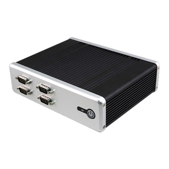
Page 7: System Overview
Rear View Connectors Label Function Note D-sub 9-pin, male Note:COM1 support RS422/485 COM1 Serial port 1 connector by BIOS setting (Factory option) HDD indicator System power indicator RJ-45 Ethernet x 2 USB2.0 USB 2.0 connector x 2 EPC-BSW Quick Reference Guide... - Page 8 EPC-BSW USB3.0 USB 3.0 connector x 4 HDMI HDMI connector DC-IN DC Power-in connector MIC IN Mic-in audio jack LINE IN Line-in audio jack LINE OUT Line-out audio jack 8 EPC-BSW Quick Reference Guide...
-
Page 9: System Dimensions
Quick Reference Guide 1.5 System Dimensions 1.5.1 Front & Top View (Unit: mm) EPC-BSW Quick Reference Guide... -
Page 10: Hardware Configuration
EPC-BSW 2. Hardware Configuration For advanced information, please refer to: 1- ECM-BSW User’s Manual 2- AUX-032 included in this manual. Note: If you need more information, please visit our website: http://www.avalue.com.tw 10 EPC-BSW Quick Reference Guide... -
Page 11: Epc-Bsw Connector Mapping
2.1.1 Serial Port 1 connector (COM1) RS-232 RS-232 Signal PIN PIN Signal DCD# DSR# RTS# RS-422/485 CTS# DTR# RS-422/485(D-sub 9pin Male) Signal 2.1.2 Serial Port 2/3/4/5 connector (COM2/3/4/5) Signal Signal DCD# DSR# RTS# CTS# DTR# EPC-BSW Quick Reference Guide 11... -
Page 12: Aux-032 User's Guide
2.54mm USB connector 5 x 2 header, pitch 2.54mm 5 x 2 header, pitch 2.0mm 2.0mm USB connector 5 x 2 header, pitch 2.0mm 2.0mm USB connector TV / Audio connector 8 x 2 header, pitch 2.54mm 12 EPC-BSW Quick Reference Guide... -
Page 13: Setting Jumper And Connector
Line out L Line out R SPK L SPK R Line in L Line in R TVGND TVGND COMP 2.0mm USB Connector (JP4) 2.0mm USB Connector (JP5) Signal PIN PIN Signal Signal PIN PIN Signal EPC-BSW Quick Reference Guide 13... -
Page 14: Installing Hard Disk & Memory (Epc-Bsw)
EPC-BSW 2.3 Installing Hard Disk & Memory (EPC-BSW) Step1. For HDD installation, please remove 8 screws to detach top cover, HDD enclosure from board & system assembly. Step2. Fix HDD using the 4 screws in the Accessory Kit. Step3. Properly install the memory module and press until properly seated.
Need help?
Do you have a question about the EPC-BSW and is the answer not in the manual?
Questions and answers