
Related Manuals for Avalue Technology EMS-BYTC2


Summary of Contents for Avalue Technology EMS-BYTC2
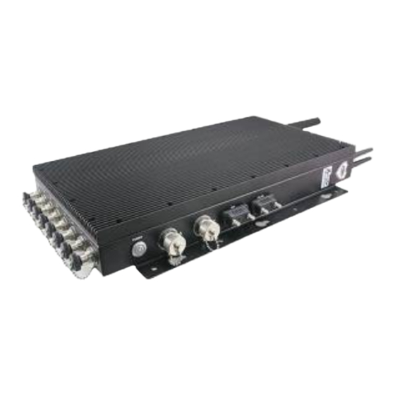
- Page 1 EMS-BYTC2 Intel® Atom™ SoC processor E3845 IP65 Fanless System Quick Reference Guide Ed – 15 October 2018 Copyright Notice Copyright 2018 Avalue Technology Inc., ALL RIGHTS RESERVED. Part No. E2017AA92A0R...
- Page 2 These answers are normally a lot more detailed than the ones we can give over the phone. So please consult the user’s manual first. To receive the latest version of the user’s manual; please visit our Web site at: http://www.avalue.com.tw/ 2 EMS-BYTC2 Quick Reference Guide...
-
Page 3: Table Of Contents
Serial Port connector (RS-485) ..................... 11 2.1.3 VGA connector (VGA) ......................12 2.1.4 USB2.0 connector (USB2.0) ....................12 2.1.5 General purpose I/O connector (GPIO) ................. 13 2.1.6 M12 A code (AI 1~AI 8) ......................13 Installing Hard Disk (EMS-BYTC2) ..............14 EMS-BYTC2 Quick Reference Guide... -
Page 4: Getting Started
Place all electronic components in a static-dissipative surface or static-shielded bag when they are not in the chassis. 1.2 Packing List 1 x EMS-BYTC2 Intel® Atom™ SoC processor E3845 IP65 Fanless System Other major components include the followings: ... -
Page 5: System Specifications
AT/ATX (ATX is default setting) Single Power ATX Support S0, S3, S4, S5 ACPI ACPI 5.0 Compliant 239.4mm x 450 mm x 60 mm Dimension Weight TBD KG Color Black EMS-BYTC2 Quick Reference Guide... - Page 6 -40 ~ 75°C (-40 ~ 167°F) IP65 Rating (System Level), CE, FCC Class A (System Level), Certification Compliance with C1D2 Explosion-proof certification OS Supported Win 7 Note: Specifications are subject to change without notice. 6 EMS-BYTC2 Quick Reference Guide...
-
Page 7: System Overview
DC Power-in connector 1.4.2 Rear View Connectors Label Function Note D-sub 9-pin, male Note:Support RS-232/422/485 by Serial port connector RS-485 BIOS setting (Default: RS-485) RJ45 RJ-45 Ethernet x 2 USB2.0 USB2.0 connector POWER Power on button VGA connector EMS-BYTC2 Quick Reference Guide... -
Page 8: Side View
EMS-BYTC2 1.4.3 Side View Connectors Label Function Note Antenna Antenna Mounting x 3 GPIO General purpose I/O connector M12 A code x 8 AI 1~AI 8 8 EMS-BYTC2 Quick Reference Guide... -
Page 9: System Dimensions
Quick Reference Guide 1.5 System Dimensions (Unit: mm) EMS-BYTC2 Quick Reference Guide... -
Page 10: Hardware Configuration
EMS-BYTC2 2. Hardware Configuration For advanced information, please refer to: 1- ECM-BYT User’s Manual Note: If you need more information, please visit our website: http://www.avalue.com.tw 10 EMS-BYTC2 Quick Reference Guide... -
Page 11: Ems-Bytc2 Connector Mapping
Quick Reference Guide 2.1 EMS-BYTC2 connector mapping 2.1.1 DC Power-in connector (DC-IN) Signal PIN PIN Signal 2.1.2 Serial Port connector (RS-485) Signal PIN PIN Signal NDCDA#_485TXN NDSRA# NRXDA_485TXP RTSA# NTXDA_485RXP NCTSA# NTXDA_485RXP NRIA# EMS-BYTC2 Quick Reference Guide 11... -
Page 12: Vga Connector (Vga)
EMS-BYTC2 2.1.3 VGA connector (VGA) Signal PIN PIN Signal Green Blue ID1/SDA HSYNC YSYNC ID3/SCL Key power Red GND Green GND Blue GND 2.1.4 USB2.0 connector (USB2.0) Signal PIN PIN Signal Shield 12 EMS-BYTC2 Quick Reference Guide... -
Page 13: General Purpose I/O Connector (Gpio)
Quick Reference Guide 2.1.5 General purpose I/O connector (GPIO) Signal PIN PIN Signal GPO1 GPI3 GPI1 GPO4 GPO2 GPI4 GPI2 GPO3 2.1.6 M12 A code (AI 1~AI 8) Signal PIN PIN Signal BNC+ BNC- EMS-BYTC2 Quick Reference Guide 13... -
Page 14: Installing Hard Disk (Ems-Bytc2)
EMS-BYTC2 2.2 Installing Hard Disk (EMS-BYTC2) Step1. Fix HDD using the 4 screws in the Accessory Kit. Step2. Insert HDD bracket and fasten it. 14 EMS-BYTC2 Quick Reference Guide...
Need help?
Do you have a question about the EMS-BYTC2 and is the answer not in the manual?
Questions and answers