Table of Contents
Advertisement
Quick Links
Operation and Maintenance Manual
SEM Model 250 Disintegrator
MAN-021 | Created 01-27-20 | ECN-00507
For sales, service, parts, and customer support, contact us:
SECURITY ENGINEERED MACHINERY
5 Walkup Drive, Westborough, MA 01581
info@semshred.com
1-508-366-1488 • Toll Free US 1-800-225-9293
www.semshred.com
Advertisement
Table of Contents

Related Manuals for SEM 250


Summary of Contents for SEM 250
- Page 1 Operation and Maintenance Manual SEM Model 250 Disintegrator MAN-021 | Created 01-27-20 | ECN-00507 For sales, service, parts, and customer support, contact us: SECURITY ENGINEERED MACHINERY 5 Walkup Drive, Westborough, MA 01581 info@semshred.com 1-508-366-1488 • Toll Free US 1-800-225-9293 www.semshred.com...
-
Page 2: Important Safety Procedures
Important Safety Procedures The Model 250 key tape & optical media disintegrator incorporates powerful, heavy duty cutting mechanisms, serious and permanent injury may result if proper precautions are not followed. 1. This equipment should never be operated by children or individuals that are untrained or incapable of understanding these safety precautions. -
Page 3: Table Of Contents
Table of Contents Important Safety Procedures ......................2 Table of Contents ........................... 3 General Assembly of the Model 250 Key Tape Unit (Table-Top Version) ........4 Installation and Power Requirements .................... 5 Disintegrator Location ..........................5 Electrical Wiring (See Page 12 for Electrical Diagram) ................5 Power Requirements .......................... -
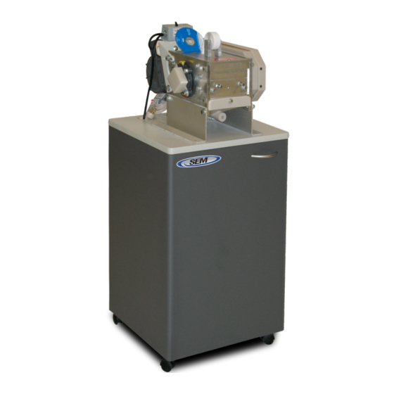
Page 4: General Assembly Of The Model 250 Key Tape Unit (Table-Top Version)
General Assembly of the Model 250 Key Tape Unit (Table-Top Version) Shown out of position Placed aside chamber and base Space requirement reference: approximately 21” x 21” x 12” high 508.366.1488 | www.semshred.com... -
Page 5: Installation And Power Requirements
Disintegrator Location The Model 250 can be located in an office area within 6 feet of a wall receptacle with a dedicated 20- amp line. It is recommended that there be unit be two to three inches between the rear of the unit and the wall. -
Page 6: Cabinet Installation And Setup
2-3 inches from wall and within six feet of dedicated 20-amp receptacle. Place Model 250 on top cover with front of unit door and the four base holes aligned with the cabinet top holes. Using the supplied bolts, place a bolt and... -
Page 7: Operation And Feed Rates
The Model 250 is not a shredder, but a rotary knife mill, which dictates how the unit is fed and the rate it can be fed. Again, the rule of thumb is “less is more” creating steady output without over feeding. -
Page 8: Troubleshooting
Troubleshooting The Model 250 will not start Check that the unit is plugged into a working receptacle. A motor thermal overload is located in the unit’s starter, located on top of the unit. As a safety feature the heater in the controls may kick out after an overload. Simply reset the control to restart the Model 250. -
Page 9: Maintenance
Maintenance Before performing any type of maintenance on the Model 250, always disconnect the unit from power and follow all safety precautions. Belt Adjustment Remove the belt guard cover. The motor is mounted on a slotted frame. Loosen the mounting bolts and adjust the motor for proper belt tension. - Page 10 The knife gap between the rotor and bed knives should be adjusted to .001-inch clearance using a feeler gauge. Note: Tool kits are available from SEM. 6. Before tightening the bed knives securely, determine that the knives are set properly by manually rotating the rotor in the reversed operating direction to ensure that no rotor knife touches the bed knives and that the proper gap has been established.
-
Page 11: Recommended Rotor And Bed Knife Setting Assembly
Recommended Rotor and Bed Knife Setting Assembly Knife Sharpening Knives may be sent to Security Engineered Machinery for sharpening or they may be sharpened by a capable machine shop in your area. When sharpening the rotor knives, they must be sharpened as a set to maintain the proper tolerance between the bed knives. -
Page 12: Notes On Knife Grinding
Notes on Knife Grinding After regrinding several times, the knives must be checked to be sure that there will still be adjustment left in the bed knives. The general rule is to place a rotor knife and bed knife back to back as shown in the diagram shown below, and then measure the total width (dimension “A”) of both knives. -
Page 13: Changing The Screen
Perforated Screen 5/64” Dia. Holes P/N: 343250SCR564 Perforated Screen 3/32” Dia. Holes P/N: 343250SCR18 Vacuum Bags (3) Pack – 230V P/N: 75060295A-3A Note: For 230V units prior to Dec 2019, contact SEM for vacuum bags for your serial number. 508.366.1488 | www.semshred.com... -
Page 14: Model 250 Vacuum Directions
Model 250 Vacuum Directions 508.366.1488 | www.semshred.com...
Need help?
Do you have a question about the 250 and is the answer not in the manual?
Questions and answers