Page 1
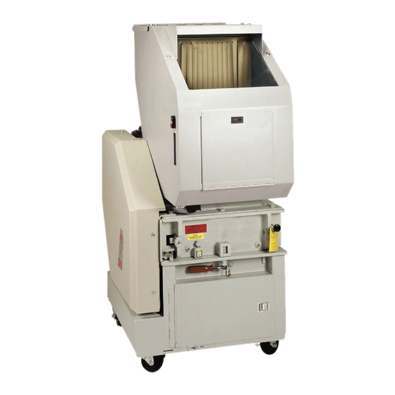
Operation and Maintenance Manual SEM Model 1012, 1012/5, 22, 22/5, 23, and 23/5 Disintegrator with Fan System Value Kits POP-0116 Rev. 0 | Created 5-9-19 | ECN-00450 For sales, service, parts, and customer support, contact us: SECURITY ENGINEERED MACHINERY 5 Walkup Drive • Westborough, MA 01581 info@semshred.com...
Proprietary Information: This document contains proprietary and confidential information of SEM, and shall not be used, disclosed or reproduced, in whole or in part, for any purpose, without the prior written consent of SEM. Title in and to this document and all information contained herein remains at all times in SEM. This information is exempted from disclosure under FOIA, as amended.
SAFETY GLASSES OR A FACE SHIELD MUST ALWAYS BE WORN when operating or servicing the machine. Although SEM machines are designed for the maximum in fly back control, caution must be used when operating near the area of the hopper feed opening in order to guard against unexpected material fly back.
This manual is intended to be used as a guide and reference for personnel who will be installing, operating, and maintaining the SEM security disintegrator. The purpose is to aid these individuals in applying efficient, proven techniques which will enhance equipment productivity.
All non-painted items subject to corrosion are coated with a quality rust preventative and the machine is then covered with heavy duty polyethylene to protect it from moisture and dirt. SEM disintegrators are normally shipped completely assembled unless the size of the machine or an agreement for special shipping arrangements requires partial disassembly.
Page 7
4. When lifting the machine, always apply lifting pressure to hopper in order to swing the machine up and back to the fully open position. For machines equipped with hydraulic jacks, utilizing the jack handle, ensure the jack needle valve is fully closed by turning it clockwise until fully seated. Insert the jack handle into the pump pivot and pump the jack piston until the cutting chamber is back to the fully open position (refer to the instruction label on the machine base).
The voltage should be the same as indicated on the silver tag in the control enclosure. If the voltage is not the same, contact the SEM service department for voltage modification instructions. Once it has been determined that the voltages are correct, it is necessary to start the motors and check for the proper direction of rotation.
3.2 Pre-Operational Checklist After all electrical and mechanical machine elements have been inspected and any defects corrected, the following pre-operational checklist should be used to ensure the disintegrator is ready for operation. • Have all installation and preparation instructions been read and followed? •...
3. Check for an open safety limit switch at the machine cutting chamber, hopper cleanout door, or any other limit switches. 4. Call the SEM service department for assistance if the machine still will not start. Have the machine serial number at hand (located on the serial number plate on the cutting chamber).
Overloading of the machine. Reduce amount of feedstock put into the machine per unit of time. Bearings have exceeded their rated life. Consult with the SEM service department for replacement instructions. Bearings are not properly installed or tightened. Consult with the SEM service department for installation instructions.
8. Service Instructions PROCEDURE - BELTS Prior to startup of this machine it is recommended that the drive belt tension is checked for proper run in deflection force as shown in illustration. After the equipment has run between 24 and 48 hours, drive belt tension must again be checked for proper operational deflection.
9. Knife Recommendations and Adjustments NOTE: The rotor and bed knives should be inspected periodically for sharpness. The sharper the knives are kept, the more efficiently and effectively the machine will operate. Waiting until the knives have been severely rounded, chipped, or otherwise damaged will result in heavy shock loading during operation causing a subsequent reduction in knife life.
Page 15
ROTOR KNIFE INSTALLATION PROCEDURE 1. Carefully block the rotor with a piece of wood to prevent it from turning. 2. Re-install the rotor knives onto the rotor. Do not torque the hex head rotor knife bolts fully at this point. Snug them down from right to left.
10. General Cutting Chamber and Knife Settings Typical Standard Cutting Chamber Assembly (3 Rotor and 2 Bed Knives) Typical Standard Cutting Chamber Assembly (5 Rotor and 2 Bed Knives) 508.366.1488 | www.semshred.com...
Model 1012/5 = 4-3/8” Model 23 & 23/5 = 5-3/4” Note: If dimension "A" is close to minimum, a new set of knives should be ordered from SEM. Please contact SEM customer service department. Dimension B: Bed knives tolerance must be held alike and parallel in sets within .010".
DESCRIPTION – BEARINGS All SEM security disintegrators and accessories are supplied with pillow block bearings which are pre-lubricated from the factory. The external mounting of bearings on the SEM security disintegrators results in a trouble free, low maintenance, and long-life bearing design.
13. Electrical Current and Tool Requirements Disintegrator - TABLE 1 DISINTEGRATOR FULL LOAD CURRENT THREE PHASE POWER Model # / HP 208V 230V 460V 575V 1012, 1012/5 @ 10 HP 30.8 26.8 13.4 10.7 1012, 1012/5 @ 15 HP 44.2 40.0 20.0 16.0...
14. Procedure to Open/Close the Disintegrator PROCEDURE TO OPEN THE DISINTEGRATOR • Allow all material to run out of the cutting chamber. • Shut OFF and LOCKOUT all power including the main disconnect switch. • Open the machine by loosening the hex coupling nut(s) at the front of the machine enough to allow for rotation of threaded swing bolts out of the clamp(s).
The serial number of the machine will also be required when ordering parts from SEM. This listing of recommended parts does not include all parts which are available for purchase. The SEM parts department can be reached at 508-366-1488 / 1-800-225-9293 or by emailing service@semshred.com.
Need help?
Do you have a question about the 1012/5 and is the answer not in the manual?
Questions and answers