
Subscribe to Our Youtube Channel
Related Manuals for Clarke CIG81212


Summary of Contents for Clarke CIG81212
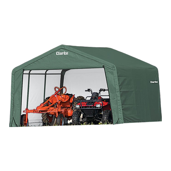
- Page 1 INSTANT SHED MODEL NO: CIG81212 (12 X 12 X 8’) PART NO: 3503584 ASSEMBLY INSTRUCTIONS ORIGINAL INSTRUCTIONS GC11/20 - Iss 2...
-
Page 2: Safety Warnings
INTRODUCTION Thank you for purchasing this CLARKE Instant Shed. Before attempting to use this product, please read this manual thoroughly and follow the instructions carefully. In doing so you will ensure the safety of yourself and that of others around you, and you can look forward to your purchase giving you long and satisfactory service. -
Page 3: Siting The Garage
POSITIONING AND INSTALLATION OF THE SHED POSITIONING THE SHED This shed is a temporary structure and is not recommended as a permanent building. It is designed to offer protection from sun, rain, light snow, tree sap and bird droppings etc. It is not designed to shelter equipment from excessively high winds or heavy snow. -
Page 4: Using The Storage Space
A supply of fresh air through the doorway will at least partly remove this issue. For long term storage of moisture sensitive belongings in all weathers, the use of a Dehumidifier may be required, such as those in the Clarke range. A suitable extension lead to a locally available power supply will be required. -
Page 5: Component Parts List
COMPONENT PARTS LIST Parts & Service: 020 8988 7400 / E-mail: Parts@clarkeinternational.com or Service@clarkeinternational.com... - Page 6 ASSEMBLY 1. Place all parts in a clear area and arrange them on the ground. 2. Remove all packaging materials and store them back in the box. Do not dispose of the packaging materials until assembly is complete. 3. Check for completeness and for any transport damage. Select a suitable location for the structure and lay out the roof parts as shown.
- Page 7 STEP 1: ASSEMBLING THE ROOF FRAME 1. Assemble the centre section of the roof using shoulder cross rails (4), 3-way peak connectors (10) and 4-way peak connector (11). Insert the rafter poles (5) into the connectors. Connect the rafter poles (5) with 3-way peak connectors (10) and 4-way peak connector (11) with fittings 15 &...
-
Page 8: Step 2: Attaching The Legs
NOTE: When using the connectors be sure to remove the protective caps first... STEP 2: ATTACHING THE LEGS 1. There are 4 corner and 2 centre legs for the whole structure. Connect the tubes 1 & 3 to create the 4 x corner legs. - Page 9 4. Repeat the same procedure for the other side. STEP 3: SQUARE AND ANCHOR THE FRAME WARNING: SERIOUS INJURY TO PERSONS OR PROPERTY COULD RESULT IF THE GARAGE IS NOT SECURELY ANCHORED, WITH EITHER THE GROUND ANCHORS SUPPLIED OR IF SITED ON CONCRETE OR TARMAC USE SUITABLE SUBSTANTIAL GROUND ANCHOR BOLTS.
- Page 10 STEP 4: ANCHORING THE FRAME CAUTION: THE STRUCTURE MUST BE WELL ANCHORED. DO NOT ATTEMPT TO INSTALL ANY OF THE FABRIC BEFORE THE FRAME IS PROPERLY ANCHORED. IF THE GROUND IS HARD OR ROCKY, PRE-DRILL HOLES BEFORE INSERTING THE ANCHORS. Four anchors (14) are provided to secure the structure to the ground.
- Page 11 Install the front door panel (20) first. During installation ensure the zipper of the front door panel (20) is closed for easier installation. 1. To make sure the strap will stay in the sleeve when assembled, thread the strap through the spindle of the ratchet. Raise and lower the handle two or three times to wind the strap onto the spindle as shown in the diagram.
- Page 12 3. Attach the other two corners of the front door panel (20) to the 3-way side connectors (7, 8) in the same way. 4. Attach the other two corners of the front door panel (20) to the 3-way side connectors (7, 8) in the same way.
- Page 13 STEP 7: INSTALLING THE MAIN COVER 1. Lay the cover on the ground next to the frame. Make sure the ends with the black straps are alongside the front door/back panels (20, 21) and the tube sleeves are facing upward. 2.
- Page 14 Make sure the cross rails are horizontal and level. Repeat the same procedure for the opposite side of the roof cover (19). Check and make sure all the bottom cross rails (6) are level and horizontal, and are all the same height from the ground. Tighten all the nuts and bolts at this stage.
- Page 15 This can take the form of an additional Auger Securing Set GA1 (already supplied with Clarke instant garages), which can add greater security for exposed, windy locations. Alternatively the Easy Hook Anchoring System GHA2, can be used to provide greater security on soft ground, available from your Clarke dealer.
Need help?
Do you have a question about the CIG81212 and is the answer not in the manual?
Questions and answers