
Subscribe to Our Youtube Channel
Related Manuals for Clarke CIG81020


Summary of Contents for Clarke CIG81020
-
Page 1: Assembly Instructions
INSTANT GARAGE MODEL NO: CIG81020 PART NO: 3503572 ASSEMBLY INSTRUCTIONS ORIGINAL INSTRUCTIONS GC1117 - ISS1... -
Page 2: Safety Instructions
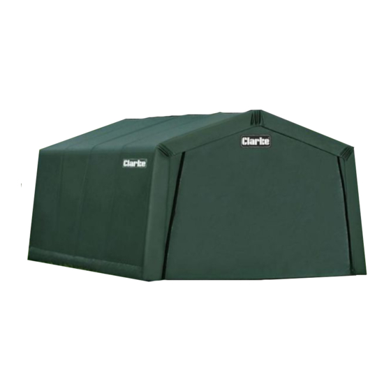
INTRODUCTION Thank you for purchasing this CLARKE Instant Garage. When erected, the CIG81020 garage will be of the dimensions show below. The product weight is 64kg packed (61 kg unpacked). Before attempting to use this product, please read this manual thoroughly and follow the instructions carefully. - Page 3 Erect your garage on a level surface. Have an overview of all parts before attempting installation. Make sure all components are available. DO NOT use this product in environments for which it is not Intended (i.e. extreme cold, high winds, extreme heat, heavy rainfall, etc). Always wear safety glasses when assembling this product.
-
Page 4: Component Parts List
COMPONENT PARTS LIST Parts & Service: 020 8988 7400 / E-mail: Parts@clarkeinternational.com or Service@clarkeinternational.com... - Page 5 ASSEMBLY 1. Place all parts in a clear area and arrange them on the ground in front of you. 2. Remove all packaging materials and place them back in the box. Do not dispose of the packaging materials until assembly is complete. 3.
- Page 6 STEP 1: PREPARING THE ROOF PARTS Select a suitable location for the garage. The layout of the roof parts is shown in diagram B. Note the differences between the connectors shown in Diagram C. (connectors are also individually numbered). Note: When installed, the welded socket for the cross rail must be below the bend.
- Page 7 STEP 2: ASSEMBLING THE ROOF 1. Assemble the roof frame by connecting the parts layout above. NOTE: The hole end on Part #3 needs to be connected to Parts #12 and #7 (See Diagram D1& D2) by the fittings #21, #23 and #24. There is a spring button on both ends of Part #4.
-
Page 8: Step 3: Attaching The Legs
STEP 3: ATTACHING THE LEGS 1. There are 10 legs for the whole shelter. Follow Drawing E1. Connect the leg tubes #1 & #10 to create the 4 x Corner legs. 2. Connect leg tubes #1 & #2 to create the 6 x Center Legs. 3. - Page 9 STEP 4: SQUARE AND ANCHOR THE FRAME 1. Check the measurements of the frame are 9'8” at both the front and back corners, as well as across the center. 2. Take a diagonal measurement as shown in Diagram F. When these two measures are equal the frame is square.
- Page 10 STEP 5: INSTALLING THE FRONT AND BACK COVERS The front cover has a zippered door to allow entry to the garage. Be sure to locate this cover at the desired end and ensure the zipper is in the closed position while installing. The back cover is a solid piece of polyethylene.
- Page 11 4. Wrap the door panel around the tube. Slip the webbing strap between the tubes and then re-connect. 5. Hook the pre-assembled ratchet tie-down to the corner bottom (#10) and tighten the ratchet until the door cover is reasonably tight. 6.
- Page 12 STEP 6: INSTALLING THE MAIN COVER 1. Lay the cover on the ground next to the frame with the inside of the cover (the side with the pockets) facing down and the strap on the front and rear of the frame. 2.
- Page 13 5. Insert the hook on the ratchet into the hole on the bent corner leg. Wind the ratchet so that the webbing overlaps itself. 6. Slide the bottom Cross Rails through the fabric pockets at each leg and re- attach with clamps at each leg. Repeat this on the other side. Push down on the cover rails to tighten the cover before tightening the bolts completely.
- Page 14 DISASSEMBLY When disassembling the garage depress the spring-loaded bar to disengage the ratchet and open the ratchet handle completely to allow the webbing strap to pull through. PLEASE RE-READ ALL WARNINGS CONTAINED ON PAGE 2/3 OF THESE INSTRUCTIONS. SAVE THESE INSTRUCTIONS FOR FUTURE USE. To dismantle, execute all instructions in reverse order.
- Page 15 GUARANTEE This product is guaranteed against faulty manufacture for a period of 12 months from the date of purchase. Please keep your receipt which will be required as proof of purchase. This guarantee is invalid if the product is found to have been abused or tampered with in any way, or not used for the purpose for which it was intended.
Need help?
Do you have a question about the CIG81020 and is the answer not in the manual?
Questions and answers