
Related Manuals for Clarke CIG81020


Summary of Contents for Clarke CIG81020
- Page 1 INSTANT GARAGE MODEL NO: CIG81020 PART NO: 3503572 ASSEMBLY INSTRUCTIONS ORIGINAL INSTRUCTIONS GC0319 - ISS4...
-
Page 2: Safety Warnings
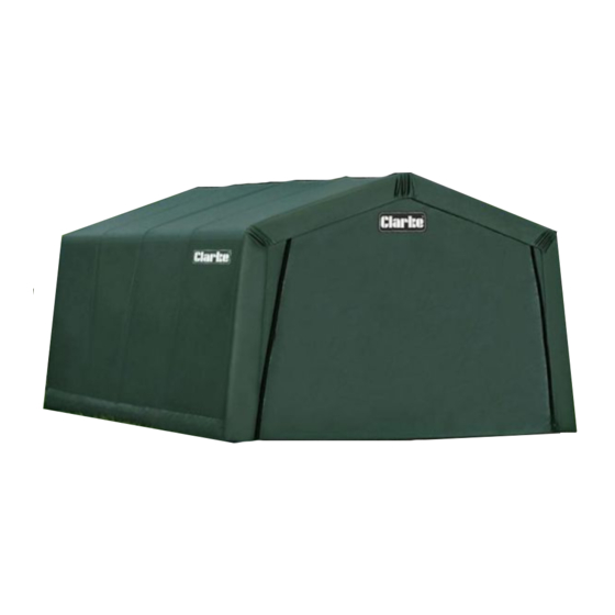
INTRODUCTION Thank you for purchasing this CLARKE Instant Garage. When erected, the CIG81020 garage will be of the dimensions show below. The product weight is 64 kg packed (62 kg unpacked). Before attempting to use this product, please read this manual thoroughly and follow the instructions carefully. -
Page 3: Positioning And Installation Of The Garage
POSITIONING AND INSTALLATION OF THE GARAGE POSITIONING THE GARAGE This garage is a temporary structure and is not recommended as a permanent building. It is designed to offer protection from sun, rain, light snow, tree sap and bird droppings etc. It is not designed to shelter equipment from excessively high winds or heavy snow. -
Page 4: Using The Storage Space
A supply of fresh air through the doorway will at least partly remove this issue. For long term storage of moisture sensitive belongings in all weathers, the use of a dehumidifier may be advantageous, such as those in the Clarke catalogue. A suitable extension lead to a locally available power supply will be required. -
Page 5: Component Parts List
COMPONENT PARTS LIST Parts & Service: 020 8988 7400 / E-mail: Parts@clarkeinternational.com or Service@clarkeinternational.com... - Page 6 ASSEMBLY WARNING: DO NOT PLACE THE PRODUCT UNDER TREES FROM WHICH HARD FRUIT SUCH AS APPLES, WALNUTS OR HEAVY PINE CONES, ETC., MAY FALL. KEEP CHILDREN AWAY DURING ASSEMBLY. THIS PRODUCT CONTAINS SMALL PARTS WHICH CAN BE SWALLOWED BY CHILDREN. DO NOT ATTEMPT TO ASSEMBLE THE PRODUCT IF ANY PARTS ARE MISSING.
- Page 7 STEP 1: PREPARING THE ROOF PARTS Select a suitable location for the garage. The layout of the roof parts is shown in diagram B. Note the differences between the connectors shown in Diagram C. (connectors are also individually numbered). Note: When installed, the welded socket for the cross rail must be below the bend.
- Page 8 STEP 2: ASSEMBLING THE ROOF 1. Assemble the roof frame by connecting the parts layout above. NOTE: The hole end on Part #3 needs to be connected to Parts #12 and #13 (See Diagram D1& D2) by the fittings #22, #24 and #25. •...
-
Page 9: Step 3: Attaching The Legs
STEP 3: ATTACHING THE LEGS There are 10 legs for the whole garage. 1. Follow Drawing E1. Connect the leg tubes #1, #2 & #6 to create the 4 x corner legs. 2. Connect leg tubes #1 & #4 to create the 6 x center legs. 3. - Page 10 STEP 4: SQUARE AND ANCHOR THE FRAME 1. Check the measurements of the frame are 10 feet at both ends as well as across the center. 2. Take a diagonal measurement as shown in Diagram F. When these two measures are equal the frame is square. Adjust the frame until they are equal to within 1".
- Page 11 STEP 5: INSTALLING THE FRONT AND BACK COVERS The front cover has a zippered door to allow entry to the garage. Be sure to locate this cover at the desired end and ensure the zipper is in the fully closed position while installing.
- Page 12 4. Repeat this with the tubes at each shoulder of the frame, wrapping the edges of the door panel around the tubes and re-connecting the frame components. 5. Hook the pre-assembled ratchet tie-down to the corner bottom (#6) and tighten the ratchet until the door cover is reasonably tight. 6.
- Page 13 STEP 6: INSTALLING THE MAIN COVER 1. Lay the cover on the ground next to the frame noting that the inside of the cover is a different colour and has pockets for the lower cross rails. The tensioning straps will be nearest the front and rear of the frame. 2.
- Page 14 6. Slide the bottom cross rails through the fabric pockets and re-attach with the clamps at each leg. Repeat this on the other side. Push down on the cover rails to tension the cover before tightening the securing bolts completely. 7.
- Page 15 This can take the form of an additional Auger Securing Set GA1 (already supplied with Clarke instant garages), which can add greater security for exposed, windy locations. Alternatively the Easy Hook Anchoring System GHA2, can be used to provide greater security on soft ground.
Need help?
Do you have a question about the CIG81020 and is the answer not in the manual?
Questions and answers