
Related Manuals for Clarke CIG1640


Summary of Contents for Clarke CIG1640
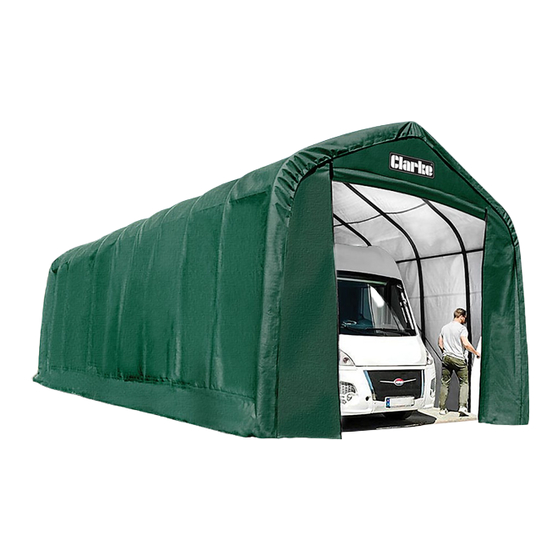
- Page 1 XX-LARGE GARAGE/WORKSHOP MODEL NO: CIG1640 PART NO: 3503596 ASSEMBLY INSTRUCTIONS ORIGINAL INSTRUCTIONS GC0821...
-
Page 2: Specifications
INTRODUCTION Thank you for purchasing this CLARKE XX Large Garage/Workshop. Before attempting to use this product, please read this manual thoroughly and follow the instructions carefully. In doing so you will ensure the safety of yourself and that of others around you, and you can look forward to your purchase giving you long and satisfactory service. -
Page 3: General Safety Warnings
GENERAL SAFETY WARNINGS WARNING: READ THESE SAFETY INSTRUCTIONS TO REDUCE THE RISK OF INJURY. RETAIN THESE INSTRUCTIONS FOR FUTURE REFERENCE. DO NOT use this product in environments for which it is not Intended (i.e. extreme cold, high winds, extreme heat, heavy rainfall or heavy snow, etc). DO NOT use open flames or cooking or heating devices inside or in close proximity to the garage including all types of stoves, gas heaters, gas lanterns, torches, fly killers, etc. -
Page 4: Care Of The Garage Structure
A supply of fresh air through the doorway will at least partly remove this issue. For long term storage of moisture sensitive belongings, the use of a dehumidifier may be required, such as those in the CLARKE range. A suitable extension lead to a locally available power supply will be required. - Page 5 COMPONENT PARTS INVENTORY Parts & Service: 020 8988 7400 / E-mail: Parts@clarkeinternational.com or Service@clarkeinternational.com...
-
Page 6: Assembly Layout
ASSEMBLY LAYOUT Parts & Service: 020 8988 7400 / E-mail: Parts@clarkeinternational.com or Service@clarkeinternational.com... - Page 7 Have an overview of all parts before attempting construction and make sure all components are supplied. Note: Some parts are listed but are not available individually as replacement parts. ASSEMBLY WARNING: DO NOT PLACE THE GARAGE UNDER TREES FROM WHICH HARD FRUIT SUCH AS APPLES, WALNUTS OR HEAVY PINE CONES, ETC., MAY FALL.
-
Page 8: Assembling The Frame
ASSEMBLING THE FRAME Assemble the End Bows and the Middle Bows as shown in Figure 1. Parts are attached using a 3" bolt (14) and nut (16) at each junction - see End and Middle Bows below. NOTE: The two End Bows are the only ones with Corner Feet (4) END BOWS Starting with two Corner Feet (4) (left side and right side) for each end, work your way up bolting connections together. - Page 9 adjustments will be done later. Insert the tapered end of each (10b) into the end of each (10a), secure with nut (16) and bolt (14). 2. At the base of that same End Bow, attach (8) to the base of (4). Swing the end of (10a+b) over to the connection of (5) and the end of (8).
- Page 10 THE REAR END BOW 1. At the base of the rear End Bow, fit the End Bottom Rail (9) to the Corner Foot (4). Attach Support Braces (10a+b) to the center of the last End Bow. Use bolts (13), washer (17), and nuts (16). Repeat on the other side of the End Bow.
- Page 11 curve. Insert Top Rail (1) inside End Top Rail (11) and attach to the Middle Bow. Continue attaching the Top Rails (1) to the Middle Bows and each other until you reach the end. Repeat these steps on the other side. Do not tighten bolts at this time.
- Page 12 SQUARING THE FRAME 1. When the garage frame is assembled and in it's final location, use the rope (19) to measure the distance between opposite corners, see Figure 7. Mark the rope and check the distance of the other two corners; the distance should be the same.
- Page 13 ANCHORING INSTRUCTIONS IMPORTANT: Due to its size, the garage needs to be anchored down very securely and the frame needs to be tight and secure. 1. From the inside of the garage, place the anchors with Steel Cable (18) on all four corners.
- Page 14 PROTECTIVE STRIPS In order to protect the fabric cover at points of wear, some adhesive tape is provided. This should be adhered to the frame at the positions shown after peeling off the adhesive backing strip. 1. Cut the backing strip into suitable lengths of approximately 9”...
-
Page 15: Cover Installation
4. Once the Top Rails (1) are into the slits on the sides and top, put the bolts (14) and nuts (16) back into all the locations that they were removed from and tighten them down. 5. Notice the white rope hanging out of the bottom of the Door Panel (21) on both sides. - Page 16 2. Use at least six people to help position the Cover (23) over the frame. It is suggested to have a person on a ladder at each end of the frame to assist with lifting. For safety, have someone to support the ladder so it will not topple over.
- Page 17 4. Loosen the four turnbuckles (20). Tie the ropes loosely to the turnbuckles (20). Check to be sure the cover is still centered and has the same amount of overlap on the front and the back. See Figure 13. 5. The area where the rope comes out of the cover (23) should be about 12" from the ground.
- Page 18 6. Pull the rope tighter, using a few knots to secure to the turnbuckle (20). Twist the turnbuckle (20) to tighten the rope. 7. Check monthly & tighten if needed. See Figure 13. 8. When the cover (23) is aligned, fasten it to the frame using the rope (19).
-
Page 19: Maintenance
MAINTENANCE 1. The cover can be cleaned with soap and water. 2. Check and tighten the turnbuckles and all hardware as needed if the garage is in regular long term use. You may need to remove and re-set the turnbuckles to allow for more strap material becoming wound around the spindle.
Need help?
Do you have a question about the CIG1640 and is the answer not in the manual?
Questions and answers