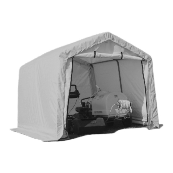
Clarke CIS8612 Assembly Instructions Manual
Instant shed (6 x 12 x 8’)
Hide thumbs
Also See for CIS8612:
- Assembly instructions manual (16 pages) ,
- Assembly instructions manual (16 pages)

Related Manuals for Clarke CIS8612


Summary of Contents for Clarke CIS8612
- Page 1 INSTANT SHED MODEL NO: CIS8612 (6 X 12 X 8’) PART NO: 3503580 ASSEMBLY INSTRUCTIONS ORIGINAL INSTRUCTIONS GC0718...
-
Page 2: Safety Instructions
INTRODUCTION Thank you for purchasing this CLARKE Instant Shed. Before attempting to use this product, please read this manual thoroughly and follow the instructions carefully. In doing so you will ensure the safety of yourself and that of others around you, and you can look forward to your purchase giving you long and satisfactory service. - Page 3 Always wear safety glasses when assembling this product. Wear gloves when working with tubing to prevent cuts or abrasions. Proper anchoring and keeping the cover tight and free of snow and debris is the responsibility of the user. Damage caused by improper anchoring are not covered under warranty. Keep all flame and heat sources away from the shelter fabric.
-
Page 4: Component Parts List
COMPONENT PARTS LIST Parts & Service: 020 8988 7400 / E-mail: Parts@clarkeinternational.com or Service@clarkeinternational.com... - Page 5 ASSEMBLY 1. Place all parts in a clear area and arrange them on the ground in front of you. 2. Remove all packaging materials and place them back in the box. Do not dispose of the packaging materials until assembly is complete. 3.
- Page 6 STEP 1: PREPARING THE ROOF PARTS Select a suitable location for the shed. The layout of the roof parts is shown in Fig.2. Note the differences between the connectors shown in Fig.3. (connectors are also individually numbered). Note: When installed, the welded socket for the cross rail must be below the bend.
-
Page 7: Step 3: Attaching The Legs
STEP 2: ASSEMBLING THE ROOF 1. Assemble the roof frame by connecting the parts layout above. Attach the roof horizontal tubes (4) and rafter tubes (1) to the 3-way connectors. 2. Use a rubber or wooden mallet to ensure all tubes are fully inserted. STEP 3: ATTACHING THE LEGS 1. - Page 8 3. Insert the centre legs and corner legs into the side connectors as in Fig.6. 4. Repeat to assemble the other side. STEP 5: SQUARE AND ANCHOR THE FRAME 1. Be sure that the frame is standing in its desired location. 2.
- Page 9 4. Take a diagonal measurement as shown in Fig.7. When these two measures are equal the frame is square. Adjust the frame until they are equal to within 1". CAUTION: THE SHELTER MUST BE WELL ANCHORED. DO NOT ATTEMPT TO INSTALL ANY OF THE FABRIC BEFORE THE FRAME IS PROPERLY ANCHORED.
- Page 10 1. To make sure the strap will stay in the sleeve when assembled, thread the webbing through the spindle of the ratchet. Raise and lower the handle two or three times to wind the webbing onto the spindle as shown in Fig.10. 2.
- Page 11 CAUTION: DO NOT THREAD THE POLES THROUGH THE SLEEVES. TO TIGHTEN, WRAP THE OUTER SLEEVES AROUND THE POLES AND TIGHTEN USING THE STRAPS PROVIDED. (Fig 12) 1. Locate the top part of the front door panel (21) near the 3-way peak connector (6) Disconnect the shoulder cross rail (4) from the 3-way peak connector (6) and pull the strap onto the connector.
- Page 12 2. Attach the other two corners of the front door panel (21) to the 3-way side connectors (9, 10) in the same way. as in Fig 14. 3. Insert the S-hook of the ratchet into the hole of the bent corner leg.
- Page 13 3. If small adjustments are needed, two people should pull the roof cover from the same side so that it does not twist. 4. Slide the cross bottom rails through the tube sleeves on one side of the roof cover. 5.
- Page 14 NOTE: Over-tightening can cause damage to straps and/or the anchor point. Do not over-tighten! The shelter is now ready for use. Check periodically and tighten ratchet tie-downs and all hardware as needed. Monthly inspection is recommended throughout usage. Parts & Service: 020 8988 7400 / E-mail: Parts@clarkeinternational.com or Service@clarkeinternational.com...
- Page 15 This can take the form of an additional Auger Securing Set GA1 (already supplied with Clarke instant garages), which can add greater security for exposed, windy locations. Alternatively the Easy Hook Anchoring System GHA2, can be used to provide greater security on soft ground.
Need help?
Do you have a question about the CIS8612 and is the answer not in the manual?
Questions and answers