Table of Contents
Advertisement
Quick Links
r
Rhino
AB and AC Unloaders
Customer Product Manual
Part 1609834−02
Issued 8/18
For parts and technical support, call the Industrial Coating
Systems Customer Support Center at (800) 433-9319 or
contact your local Nordson representative.
This document is subject to change without notice.
Check http://emanuals.nordson.com for the latest version.
NORDSON CORPORATION AMHERST, OHIO USA
Advertisement
Table of Contents

Subscribe to Our Youtube Channel
Related Manuals for Nordson Rhino AB


Summary of Contents for Nordson Rhino AB
- Page 1 For parts and technical support, call the Industrial Coating Systems Customer Support Center at (800) 433-9319 or contact your local Nordson representative. This document is subject to change without notice. Check http://emanuals.nordson.com for the latest version. NORDSON CORPORATION AMHERST, OHIO USA...
- Page 2 Contact Us Notice This is a Nordson Corporation publication which is protected by copyright. Nordson Corporation welcomes requests for information, comments, and Original copyright date 2018. No part of this document may be inquiries about its products. General information about Nordson can be...
-
Page 3: Table Of Contents
........Part 1609834−02 E 2018 Nordson Corporation... - Page 4 Reference Documentation ....... . Part 1609834−02 E 2018 Nordson Corporation...
-
Page 5: Safety
Regulations and Approvals Make sure all equipment is rated and approved for the environment in which it is used. Any approvals obtained for Nordson equipment will be voided if instructions for installation, operation, and service are not followed. Part 1609834−02... -
Page 6: Personal Safety
If you suffer a fluid injection injury, seek medical care immediately. If possible, provide a copy of the SDS for the injected fluid to the health care provider. Part 1609834−02 E 2018 Nordson Corporation... -
Page 7: Fire Safety
Do not smoke, weld, grind, or use open flames where flammable materials are being used or stored. Do not heat materials to temperatures above those recommended by the manufacturer. Make sure heat monitoring and limiting devices are working properly. Part 1609834−02 E 2018 Nordson Corporation... -
Page 8: Halogenated Hydrocarbon Solvent Hazards
Clean, maintain, test, and repair equipment according to the instructions in your equipment documentation. Use only replacement parts that are designed for use with original equipment. Contact your Nordson representative for parts information and advice. Halogenated Hydrocarbon Solvent Hazards Do not use halogenated hydrocarbon solvents in a pressurized system that contains aluminum components. -
Page 9: Safety Labels
Avoid servicing this equipment from the rear. If service from the rear is unavoidable, lock out all electric and pneumatic power sources. WARNING: Lock out all electrical and pneumatic power sources. DO NOT place hands or body between the platen/drum and crossbar. Part 1609834−02 E 2018 Nordson Corporation... - Page 10 Safety AC UNLOADER AB UNLOADER 10016369 1609049 Figure 1-1 Safety Label Location Part 1609834−02 E 2018 Nordson Corporation...
-
Page 11: Overview
Pressure Relief Valve Assembly (AC unloader only): Used in the air supply circuit to limit the maximum pressure to the pump air motor, thus limiting the maximum pump output pressure. Part 1609834−02 E 2018 Nordson Corporation... -
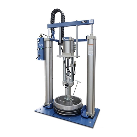
Page 12: Ab Unloader
9. Pail hold-down 2. Pneumatic control module 6. Base plate 10. Blow-off check valve 7. Material outlet port 11. Follower plate module 3. Solvent chamber 4. Solvent chamber drain port 8. Bleed valve 12. Pump Part 1609834−02 E 2018 Nordson Corporation... -
Page 13: Ac Unloader
10. Blow-off check valve 2. Pneumatic control module 7. Material outlet port 11. Follower plate module 3. Solvent chamber 8. Bleed valve 12. Pump 5. Bleed port 9. Drum-centering shoes 13. Pressure relief valve Part 1609834−02 E 2018 Nordson Corporation... -
Page 14: Pneumatic Control Module
S Ram Down position lowers the elevator and follower plate assembly into the material container. S Neutral position stops elevator movement. Neutral is not a locked and secured position. The follower plate may drift downward over time. Part 1609834−02 E 2018 Nordson Corporation... - Page 15 4. Material container blow-off valve 7. Pneumatic reset valve 2. Control module lockout valve 5. Air motor lockout valve 8. Elevator air pressure gauge 3. Elevator air regulator 6. Air motor pressure gauge 9. Elevator control valve Part 1609834−02 E 2018 Nordson Corporation...
-
Page 16: Control Module Symbols And Icons
Pressure Measurement Pneumatic Push Button Pressure Control Reset Symbol Symbol Symbol On Icon Off Icon Material Container Elevator Icon Down Icon Up Icon Air Motor Icon Blow−Off Icon Figure 2-4 Control Module Symbols and Icons Part 1609834−02 E 2018 Nordson Corporation... -
Page 17: Ab Pump
5. Air motor 2. Split coupling 4. Hydraulic section 6. Solvent chamber Table 2-3 Rhino AB Pump Components Item Description Air Motor Valves: Control the direction of the pump drive train. Split Coupling: Connects the air motor coupling shaft to the hydraulic section plunger rod. -
Page 18: Theory Of Operation
The pilot valve sends a positive continuous signal to the main air motor control valve for each direction of travel. Main Air Control Valve Pilot Valve 10016282_125 Figure 2-6 Rhino 125-mm Air Motor Part 1609834−02 E 2018 Nordson Corporation... -
Page 19: Hydraulic Section − Suction Stroke
A small amount of leakage is normal. If the solvent chamber (4) fills quickly and overflows the packings need to be replaced. Both upper and lower packings should be replaced at the same time. Part 1609834−02 E 2018 Nordson Corporation... - Page 20 STROKE Î Î Î Î Î Î Î Î Î Î 10014972 Figure 2-7 Rhino AB Pump Operation 1. Connecting rod 4. Solvent chamber 7. Pressure ball check 2. Packing gland 5. Solvent chamber drain port 8. Siphon ball check 3.
-
Page 21: Ac Pump
Shovel: Forces material into the hydraulic section. Air Motor Valves: Control the direction of the air motor shaft. Hydraulic Section: Pressurizes the material and forces it out of the pump. Part 1609834−02 E 2018 Nordson Corporation... -
Page 22: Theory Of Operation
Air Motor Cover Pilot Valve Main Air Control Valve 10016282_100 Figure 2-9 Rhino 100-mm Air Motor NOTE: The air motor cover and fasteners are not included in the packaged air motor kits. Part 1609834−02 E 2018 Nordson Corporation... -
Page 23: Hydraulic Section
The solvent chamber (2) surrounds the plunger (1). The chamber contains solvent chamber fluid that lubricates the plunger and packing gland (3) seals. This fluid keeps material from hardening on the plunger and minimizes wear on the packing gland seals. Part 1609834−02 E 2018 Nordson Corporation... - Page 24 Figure 2-10 Standard Hydraulic Sections, Rhino AC Pump 1. Plunger 4. Piston/upper check 7. Material outlet port 2. Solvent chamber 5. Lower check 8. Shovel 3. Packing gland 6. Follower plate 9. Shovel check plate Part 1609834−02 E 2018 Nordson Corporation...
-
Page 25: Bleed Valve
WARNING: Do not open the bleed valve more than three turns. The bleed valve and material may be forced from the valve body. AB UNLOADER AC UNLOADER Bleed Valve Bleed Valve 10014972 10015086 Figure 2-11 Bleed Valve Location NOTE: AB unloader is shown enlarged for clarity. Part 1609834−02 E 2018 Nordson Corporation... -
Page 26: Follower Modules
When the elevator is in the Ram Up position and the blow-off valve is triggered, air flows under the follower plate (5). This pressure keeps the container on the base plate as the ram cylinders move the pump and follower upward. Part 1609834−02 E 2018 Nordson Corporation... - Page 27 2-17 Overview AC FOLLOWER MODULE AB FOLLOWER MODULE Figure 2-12 Follower Modules 1. Bleeder stem 3. Hydraulic section 5. Follower plate 2. Bleeder stem adapter 4. Blow-off check valve port Part 1609834−02 E 2018 Nordson Corporation...
-
Page 28: Accessories
AB and AC Unloader Container Level Light Tower See Figure 2-13. The container level light tower indicates when the container is low or empty. The low indicator has a customer-adjustable location. 10016801 Figure 2-13 Light Tower Part 1609834−02 E 2018 Nordson Corporation... -
Page 29: Container Hold-Down
The container hold-down is used on the AB unloader. The container hold-down is vertically and horizontally adjustable, so it is able to accommodate a wide variety of container diameters. CONTAINER HOLD-DOWN EXPLODED VIEW 10014972 Figure 2-14 Container Hold-Down Part 1609834−02 E 2018 Nordson Corporation... -
Page 30: Material Output Gauge
The material output gauge can be used on the AB and AC unloaders. The material output gauge connects to the hydraulic section pump outlet manifold and measures the material output pressure. Hydraulic Section Pump Outlet Manifold 10017101 Figure 2-15 Material Output Gauge Part 1609834−02 E 2018 Nordson Corporation... -
Page 31: Specifications
2-21 Overview Specifications WARNING: Use Nordson or equivalent nylon or PTFE fluid hoses with electrical continuity between fittings. Hoses must be capable of withstanding the maximum output pressure of the pump. Use flexible hoses between the pump and the fluid system to dampen vibrations. - Page 32 2-22 Overview This page intentionally left blank. Part 1609834−02 E 2018 Nordson Corporation...
-
Page 33: Installation
Installation Procedure CAUTION: Read and understand this entire section before performing any installation procedures. Contact a local Nordson representative with questions regarding the installation of this equipment. WARNING: Personnel performing these procedures must know how to safely operate the unloader elevator controls. -
Page 34: Unpack The Unloader
Examine all surfaces for evidence of dents, scratches, corrosion, and other physical damage. Report any damage to a Nordson representative. Install the Unloader 1. Position the unloader at a location that allows access to the front of the unloader. Secure the unloader to the floor in the desired location using the four holes provided in the frame base plate. -
Page 35: Operation
1.5 in. (38 mm) from the top of the solvent chamber. AB unloader: Pour the solvent chamber fluid into the solvent chamber until it is within 1 in. (25.4 mm) from the top of the solvent chamber. Part 1609834−02 E 2018 Nordson Corporation... - Page 36 14. Place the elevator control valve (9) in the Ram Down position to force material into the pump. 15. Set the air motor pressure to 0 psi, then open the air motor lockout valve (5). Part 1609834−02 E 2018 Nordson Corporation...
- Page 37 18. Trigger the applicator(s) to bleed off air in the lines. 19. Adjust the air motor regulator (1) to increase pressure until the applicator dispenses material that flows smoothly, continuously, and without air bubbles. Part 1609834−02 E 2018 Nordson Corporation...
-
Page 38: Control Module Components
S Ram Down position lowers the elevator and follower plate assembly into the material container. S Neutral position stops elevator movement. Neutral is not a locked and secured position. The follower plate may drift downward over time. Part 1609834−02 E 2018 Nordson Corporation... - Page 39 4. Material container blow-off valve 7. Pneumatic reset valve 2. Control module lockout valve 5. Air motor lockout valve 8. Elevator air pressure gauge 3. Elevator air regulator 6. Air motor pressure gauge 9. Elevator control valve Part 1609834−02 E 2018 Nordson Corporation...
-
Page 40: Container Change Procedure
13. Place the elevator control valve (4) in Ram Down to apply downward force to the elevator. 14. Decrease the air motor regulator (2) to 0 psi, then set the air motor lockout valve (1) to On. Part 1609834−02 E 2018 Nordson Corporation... - Page 41 5. Follower plate seals 9. Bleeder stem 2. Air motor regulator 6. Container 10. Follower module 3. Material container blow-off button 7. Bleed valve 11. Unloader base plate 4. Elevator control valve 8. Reset button Part 1609834−02 E 2018 Nordson Corporation...
-
Page 42: Pump Operation
NOTE: System pressure requirements may need to be limited due to component pressure ratings or other system requirements. A different pressure relief valve of the desired pressure range can be selected to prevent the system from being over pressurized. Part 1609834−02 E 2018 Nordson Corporation... -
Page 43: Elevator And Blow-Off Air Supply
The air pressure forces the container off of the follower plate. The elevator control valve must be in the Ram Up position for the blow-off valve push button to activate air pressure to the bottom of the follower. Part 1609834−02 E 2018 Nordson Corporation... -
Page 44: Maintenance
Replace the solvent chamber fluid. If necessary, use a pick to Solvent Chamber remove any material blocking the outlet port. Refer to the Pumps section in this manual for maintenance − − − − − − Pump procedures. Part 1609834−02 E 2018 Nordson Corporation... -
Page 45: Troubleshooting
Follow the safety instructions in this document and all other related documentation. These troubleshooting procedures cover only the most common problems. If the problem cannot be solved with the information given here, contact a local Nordson representative for assistance. Problem Possible Cause Corrective Action... - Page 46 Worn magnetic proximity sensors These valves cannot be repaired and referenced in these or pilot valve. must be replaced. Order new valves. procedures. Refer to the Pumps section in this manual for ordering information. Continued... Part 1609834−02 E 2018 Nordson Corporation...
- Page 47 If no air is present, replace the blow-off valve. If air is present, make sure that it is flowing out of the bottom of the follower plate when tubing is reconnected. Continued... Part 1609834−02 E 2018 Nordson Corporation...
- Page 48 Clean or replace the hose if necessary. 4. If steps 1, 2, and 3 do not solve the problem, remove and rebuild the pump. Refer to the pump manuals for the procedures. Part 1609834−02 E 2018 Nordson Corporation...
-
Page 49: Repair
Rhino AB Lower Check Replacement 1613134 Rhino AB Packing Gland Replacement 1613099 Rhino AB Pump 1614146 Rhino AB Soft Goods Replacement Kit 1613476 Rhino AB Upper Check Valve Replacement 1613133 Rhino Bleed Valve 1612230 Rhino SD3/XD3 5-Gallon Dual-Post Container Hold-Down... - Page 50 Repair This page intentionally left blank. Part 1609834−02 E 2018 Nordson Corporation...
-
Page 51: Parts
Parts Section 7 Parts Introduction To order parts, call the Nordson Industrial Coating Systems Customer Support Center at (800) 433-9319 or contact your local Nordson representative. Reference Documentation Refer to the applicable document to order parts. Document Title Doc. No. - Page 52 Parts This page intentionally left blank. Part 1609834−02 E 2018 Nordson Corporation...
Need help?
Do you have a question about the Rhino AB and is the answer not in the manual?
Questions and answers