
Related Manuals for Nordson DuraBlue D4L


Summary of Contents for Nordson DuraBlue D4L
- Page 1 DuraBlue Adhesive Melters Models D4L, D10L, and D16L Customer Product Manual Part 1032059B Issued 07/03 NORDSON CORPORATION • DULUTH, GEORGIA • USA www.nordson.com...
- Page 2 This is a Nordson Corporation publication which is protected by copyright. Original copyright date 2002. No part of this document may be photocopied, reproduced, or translated to another language without the prior written consent of Nordson Corporation. The information contained in this publication is subject to change without notice. 2003 All rights reserved.
-
Page 3: Table Of Contents
......... Manual 41-DURABLUE-MA-02 Part 1032059B E 2003 Nordson Corporation... - Page 4 Adjusting the Pressure Control Valve ......3-22 Manual 41-DURABLUE-MA-02 E 2003 Nordson Corporation Part 1032059B...
- Page 5 ....... 7-14 Manual 41-DURABLUE-MA-02 Part 1032059B E 2003 Nordson Corporation...
- Page 6 ..........B-18 Manual 41-DURABLUE-MA-02 E 2003 Nordson Corporation Part 1032059B...
-
Page 7: Safety
CAUTION: (Used without the safety alert symbol) Indicates a potentially hazardous situation that, if not avoided, can result in damage to equipment or property. Manual 41-DURABLUE-MA-02 Part 1032059B E 2003 Nordson Corporation... -
Page 8: Responsibilities Of The Equipment Owner
Provide appropriate emergency and first aid equipment. Conduct safety inspections to ensure required practices are being followed. Re-evaluate safety practices and procedures whenever changes are made to the process or equipment. Manual 41-DURABLUE-MA-02 E 2003 Nordson Corporation Part 1032059B... -
Page 9: User Qualifications
Familiarize yourself with the location and meaning of the safety warning labels and tags affixed to the equipment. Refer to Safety Labels and Tags at the end of this section. If you are unsure of how to use the equipment, contact your Nordson representative for assistance. Manual 41-DURABLUE-MA-02... -
Page 10: Installation Practices
Refer to the Material Safety Data Sheet (MSDS) for the material. If the required installation configuration does not match the installation instructions, contact your Nordson representative for assistance. Position the equipment for safe operation. Observe the requirements for clearance between the equipment and other objects. -
Page 11: Maintenance And Repair Practices
Use only new or factory-authorized refurbished replacement parts. Read and comply with the manufacturer’s instructions and the MSDS supplied with equipment cleaning compounds. NOTE: MSDSs for cleaning compounds that are sold by Nordson are available at www.nordson.com or by calling your Nordson representative. -
Page 12: Equipment Safety Information
NOTE: Government regulations and industry standards dictate specific requirements for the isolation of hazardous energy sources. Refer to the appropriate regulation or standard. Manual 41-DURABLUE-MA-02 E 2003 Nordson Corporation Part 1032059B... -
Page 13: Disabling The Guns
General Safety Warnings and Cautions Table 1-1 contains the general safety warnings and cautions that apply to Nordson hot melt and cold adhesive equipment. Review the table and carefully read all of the warnings or cautions that apply to the type of equipment described in this manual. - Page 14 WARNING: Hazardous vapors! Before processing any polyurethane reactive (PUR) hot melt or solvent-based material through a compatible Nordson melter, read and comply with the material’s MSDS. Ensure that the material’s processing temperature and flashpoints will not be exceeded and that all requirements for safe handling, ventilation, first aid, and personal protective equipment are met.
- Page 15 Equipment Warning or Caution Type WARNING: Risk of fire or explosion! Nordson cold adhesive equipment is not rated for use in explosive environments and should not be used with solvent-based adhesives that can create an explosive atmosphere when processed. Refer to the MSDS for the adhesive to determine its processing characteristics and limitations.
-
Page 16: Other Safety Precautions
The installation kit provided with the melter may contain label overlays that are printed in a variety of languages. If required by governing safety regulations, apply the appropriate overlay to the text portion of the labels shown in Figure 1-1. Manual 41-DURABLUE-MA-02 E 2003 Nordson Corporation Part 1032059B... - Page 17 Item Description WARNING: Hazardous voltage. Disconnect all power supply connections before servicing. CAUTION: Burn hazard. Hot surfaces. WARNING: Hazardous voltage. Disconnect all power supply connections before servicing. CAUTION: Burn hazard. Hot surfaces. Manual 41-DURABLUE-MA-02 Part 1032059B E 2003 Nordson Corporation...
- Page 18 1-12 Safety This page intentionally left blank. Manual 41-DURABLUE-MA-02 E 2003 Nordson Corporation Part 1032059B...
-
Page 19: Introduction
DuraBlue 10 L (D10L), and DuraBlue 16 L (D16L) adhesive melters. When necessary, the reader is referred to the documentation supplied with other Nordson products or products supplied by third parties. With the exception of tank capacity, hose/gun capacity, and exterior appearance, all DuraBlue melters are function identically. -
Page 20: Other Sources Of Information
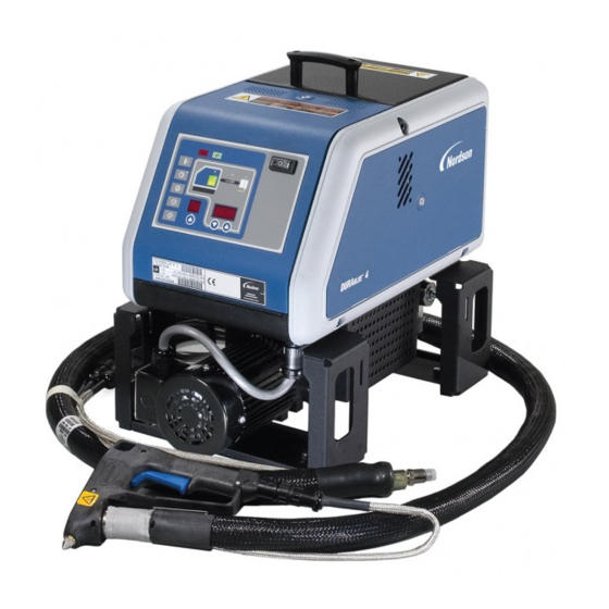
Product Description See Figure 2-1. Nordson DuraBlue adhesive melters are used in conjunction with Nordson hot melt hoses and guns to create a hot melt application system. The melter liquifies solid-form hot melt and maintains the hot melt at the desired temperature. -
Page 21: Intended Use
230 _C (450 _F) for 240 VAC melters or below 200 _C (400 _F) for 120 VAC melters Be used with compatible hot melt hoses and guns that are manufactured by Nordson Corporation Be used in non-explosive environments Limitations of Use Use DuraBlue melters only for the purpose for which they are designed. -
Page 22: Modes Of Operation
The model and part number are indicated on the equipment identification plate that is located on the front of the melter. Figure 2-2 Equipment identification plate Manual 41-DURABLUE-MA-02 E 2003 Nordson Corporation Part 1032059B... -
Page 23: Key Components
2. Control panel (see Figure 2-4) 6. Hose/gun receptacles 10. Filter 3. Tank lid 7. Tank isolation valve 11. Pump (D10/D16 only) 4. Side panels 12. Mounting bracket 8. Manifold 13. Motor Manual 41-DURABLUE-MA-02 Part 1032059B E 2003 Nordson Corporation... - Page 24 Introduction Figure 2-4 Control panel 1. Fault LED 4. Control switch 6. Left display and scroll key 2. Ready LED 5. Right display and scroll keys 7. Function keys 3. Component keys/LEDs Manual 41-DURABLUE-MA-02 E 2003 Nordson Corporation Part 1032059B...
-
Page 25: Optional Equipment
Pressure control valve knob that replaces the hex screw pressure adjustment with a hand knob. Refer to Section 7, Parts, for a complete list of optional equipment. Manual 41-DURABLUE-MA-02 Part 1032059B E 2003 Nordson Corporation... - Page 26 Introduction This page intentionally left blank. Manual 41-DURABLUE-MA-02 E 2003 Nordson Corporation Part 1032059B...
-
Page 27: Installation
Procedural variations or special considerations are explained in the additional information table that follows most procedures. Where applicable, some table entries also contain cross-reference information. Additional information tables are indicated by the symbol shown to the left. Manual 41-DURABLUE-MA-02 Part 1032059B E 2003 Nordson Corporation... -
Page 28: Installation Tasks
The instructions provided in this section are intended to be used by personnel who have experience in the following subjects: Hot melt application processes Industrial power and control wiring Industrial mechanical installation practices Basic process control and instrumentation Manual 41-DURABLUE-MA-02 E 2003 Nordson Corporation Part 1032059B... -
Page 29: Installation Requirements
(35.73 in.) door and tank lid are fully opened. Minimum vertical space required for the 861 mm 623 mm melter when the tank lid is at its highest point. (33.90 in.) (24.54 in.) Manual 41-DURABLUE-MA-02 Part 1032059B E 2003 Nordson Corporation... -
Page 30: Electrical Power
The melter must be installed where it will be in conformance with the ventilation requirements specified in the Material Safety Data Sheet for the hot melt being used. Manual 41-DURABLUE-MA-02 E 2003 Nordson Corporation Part 1032059B... -
Page 31: Unpacking The Melter
Before starting the installation, remove the melter from the pallet, locate the installation kit, and inspect the melter for damaged and missing parts. Report any problems to your Nordson representative. Contents of the Installation Kit The installation kit provided with the melter contains the components shown in Figure 3-2. -
Page 32: Mounting The Melter
NOTE: The bolt mounting pattern of DuraBlue melters can be adapted to that of many other Nordson melters. Refer to Table 3-2. Mounting holes 9.53 mm (.38 in.) - Page 33 Installation Table 3-2 Comparison of DuraBlue Melter Dimensions with Other Melter Dimensions 3500 LS10 3100 3700 Dimension KB20 LS20 3400 3830 KB10 3930 • • • • • • • • Manual 41-DURABLUE-MA-02 Part 1032059B E 2003 Nordson Corporation...
-
Page 34: Connecting The Electrical Service
DuraBlue melters operating at 200–240 volts are shown in Table 3-3. Table 3-3 Maximum Amperages for 200–240 Volt Melters Model Maximum Amperage D10L D16L NOTE: The ground conductor is the striped wire. Melter with attached power cable Manual 41-DURABLUE-MA-02 E 2003 Nordson Corporation Part 1032059B... - Page 35 Installation This page intentionally left blank. Manual 41-DURABLUE-MA-02 Part 1032059B E 2003 Nordson Corporation...
-
Page 36: Connecting Hoses And Guns
Hose ports manifold. (Filtered and nonfiltered manifolds Refer to the user’s guide provided with each Nordson hose. The guide shown) contains important information about routing and installing the hose. Save all of the plugs that were removed from the hose ports. A plug will need to be reinstalled into a hose port if a hose is later removed. - Page 37 Connecting a switched handgun hose or footswitch To connect guns Observe the following guidelines: For information about choosing the most appropriate Nordson hot melt gun for your manufacturing process, refer to the latest edition of Nordson’s hot melt dispensing equipment Replacement Parts Catalog or contact your Nordson representative.
-
Page 38: Setting Up The Melter
If you need to make changes to the factory setup or if you want to learn about other operating parameters, go to the next part in this section, Operating Parameters. Manual 41-DURABLUE-MA-02 E 2003 Nordson Corporation Part 1032059B... - Page 39 A group of parameters that control the melter’s clock. Seven-day Clock The clock is used to automatically turn the heaters on Disabled 50 to 77 and off and to place the melter into the standby mode. Manual 41-DURABLUE-MA-02 Part 1032059B E 2003 Nordson Corporation...
-
Page 40: Operating Parameters
Reading or Editing Operating Parameters Regardless of whether a parameter’s value is editable or not, the procedure for accessing each parameter in order to read or edit its current value is the same. Manual 41-DURABLUE-MA-02 E 2003 Nordson Corporation Part 1032059B... - Page 41 8. Repeat step 5 through step 7 to read or change the next sequential parameter number or press the Setup key to exit the setup mode. Manual 41-DURABLUE-MA-02 Part 1032059B E 2003 Nordson Corporation...
- Page 42 0000 to 2359 —:— Schedule for Monday 0–7 Schedule for Tuesday 0–7 Schedule for Wednesday 0–7 Schedule for Thursday 0–7 Schedule for Friday 0–7 Schedule for Saturday 0–7 Schedule for Sunday 0–7 Manual 41-DURABLUE-MA-02 E 2003 Nordson Corporation Part 1032059B...
- Page 43 If password protection is enabled, the melter will Appendix B, Parameter 10 return to the password protected mode whenever you exit the setup mode. Manual 41-DURABLUE-MA-02 Part 1032059B E 2003 Nordson Corporation...
-
Page 44: Set-Point Temperature Of The Tank, Hoses, And Guns
The right display indicates all dashes (----) and the LEDs on the tank, hose, and gun keys turn green. 3. Press a right-display scroll key. The right display flashes. Left display and scroll key Manual 41-DURABLUE-MA-02 E 2003 Nordson Corporation Part 1032059B... - Page 45 Each component begins to heat or cool to the new global set-point temperature and the melter returns to the automatic scan mode. When all of the components reach the global set-point temperature, the ready LED turns on (green). Ready LED Manual 41-DURABLUE-MA-02 Part 1032059B E 2003 Nordson Corporation...
-
Page 46: Review Parameter And Set-Point Temperature Changes
Each press of a scroll key displays a progressively older log Component key LEDs entry. 4. Press the Setup key to return to the automatic scan mode. Scrolling through the log Manual 41-DURABLUE-MA-02 E 2003 Nordson Corporation Part 1032059B... - Page 47 Unused log entries in the change history log are indicated by “P-_” in the right display. To view how many heater hours have elapsed since a specific change (displayed) was made, simultaneously press both of the right-display scroll keys. Manual 41-DURABLUE-MA-02 Part 1032059B E 2003 Nordson Corporation...
-
Page 48: Installing Optional Equipment
With the line running and the guns dispensing adhesive, turn the adjustment screw on the pressure control valve clockwise to increase the adhesive output counterclockwise to decrease the adhesive output Adjusting the pressure control valve Manual 41-DURABLUE-MA-02 E 2003 Nordson Corporation Part 1032059B... -
Page 49: Operation
Procedural variations or special considerations are explained in the additional information table that follows most procedures. Where applicable, some table entries also contain cross-reference information. Additional information tables are indicated by the symbol shown to the left. Manual 41-DURABLUE-MA-02 Part 1032059B E 2003 Nordson Corporation... -
Page 50: More About Heated Components
(or otherwise identify) the auxiliary device as to the hose or gun position number that represents the device. The control panel will identify such devices as a hose or gun, regardless of what the device actually is. Manual 41-DURABLUE-MA-02 E 2003 Nordson Corporation Part 1032059B... -
Page 51: Filling The Tank
2. Use a scoop to fill the tank with hot melt. Table 4-1 lists the tank capacity of each DuraBlue melter. NOTE: Nordson Corporation recommends that the tank be kept at least one-half full while the melter is operating. 3. Close the tank lid when you are finished filling the tank. -
Page 52: Starting The Melter
Ready LED NOTE: You can change the way the pump key operates by changing parameter 8 (automatic pump on). Refer to Appendix B, Operating Parameters. Pump key Manual 41-DURABLUE-MA-02 E 2003 Nordson Corporation Part 1032059B... - Page 53 If the seven-day clock was on prior to the power failure, the melter will restart in the mode dictated by the clock schedule at the time the melter restarts. Manual 41-DURABLUE-MA-02 Part 1032059B E 2003 Nordson Corporation...
-
Page 54: Monitoring The Melter
Refer to Monitor Melter Faults and Using Melter Function Keys later in this section for information about melter faults and using the seven-day clock and standby functions. Refer to Appendix B, Parameter 4, for information about the ready delay. Manual 41-DURABLUE-MA-02 E 2003 Nordson Corporation Part 1032059B... -
Page 55: Monitor Component Temperatures
3. When the position number of the desired component appears in the left display, observe the right display to determine the component’s actual temperature. LEDs on component keys Manual 41-DURABLUE-MA-02 Part 1032059B E 2003 Nordson Corporation... - Page 56 UP scroll key. Holding down the scroll key while the melter is in the automatic scan mode reveals the set-point of each component that is scanned. Manual 41-DURABLUE-MA-02 E 2003 Nordson Corporation Part 1032059B...
- Page 57 Operation This page intentionally left blank. Manual 41-DURABLUE-MA-02 Part 1032059B E 2003 Nordson Corporation...
-
Page 58: Monitor Melter Faults
RTD analog-to-digital converter could not be F4/7 Melter stops functioning calibration calibrated Communication failure between main board and F4/8 Main board feedback Melter stops functioning F4/A Thermostat Melter stops functioning Tank or pump thermostat is open Manual 41-DURABLUE-MA-02 E 2003 Nordson Corporation Part 1032059B... -
Page 59: How F1, F2, And F3 Faults Are Handled
LED will turn off, the red fault LED will turn on, the Fault LED (red) heaters turn off, and the melter records the fault in the fault log. Refer to To review the fault log later in this part. Manual 41-DURABLUE-MA-02 Part 1032059B E 2003 Nordson Corporation... -
Page 60: How F4 Faults Are Handled
2. Return the melter to the automatic scan mode by pressing the Setup key twice. 3. Cycle the control switch. 4. Press the Heater key to turn on the heaters. Heater key Manual 41-DURABLUE-MA-02 E 2003 Nordson Corporation Part 1032059B... - Page 61 235 _C (458 _F), an immediate F3 fault will occur (no two-minute monitoring period). If F4 appears in the right display when you press the clock key, the internal clock function has failed. Manual 41-DURABLUE-MA-02 Part 1032059B E 2003 Nordson Corporation...
- Page 62 4 = Hose 4 or gun 4 3 = Component over temperature 5 = Hose 5 or gun 5 4 = Processor or electrical failure 4 = Processor or electrical failure 6 = Hose 6 or gun 6 Manual 41-DURABLUE-MA-02 E 2003 Nordson Corporation Part 1032059B...
- Page 63 When an F1 fault is the result of a hose/gun pair being disconnected from the melter, two fault log entries are created. The first entry is for the gun and the second entry is for the hose. Manual 41-DURABLUE-MA-02 Part 1032059B E 2003 Nordson Corporation...
-
Page 64: Adjusting Component Temperatures
5. Press the Tank key. All components begin to heat or cool to the new global set-point temperature. When all of the components reach their set-point temperature, the ready LED turns on (green). Ready LED Manual 41-DURABLUE-MA-02 E 2003 Nordson Corporation Part 1032059B... - Page 65 5. Press the left-display scroll key. The hoses or the guns begin to heat or cool to their new set-point temperature. Manual 41-DURABLUE-MA-02 Part 1032059B E 2003 Nordson Corporation...
- Page 66 To register the new set-point temperature and return to the automatic scan mode, go to step 6. 6. Press any component key (tank, hose, or gun). The selected component begins to heat or cool to its new set-point temperature. Manual 41-DURABLUE-MA-02 E 2003 Nordson Corporation Part 1032059B...
- Page 67 The melter stores a record of the last Section 3, Installation, Review ten changes made to the set-point Parameter and Set-point temperatures (and operating parameters) in Temperature Changes the change history log. Manual 41-DURABLUE-MA-02 Part 1032059B E 2003 Nordson Corporation...
-
Page 68: Using Melter Function Keys
LED is green. If the automatic pump on feature (parameter 8) is disabled, then the pump key must be used to start the pump when the melter is ready. Manual 41-DURABLUE-MA-02 E 2003 Nordson Corporation Part 1032059B... -
Page 69: Setup Key
The clock will still operate when the melter is faulting or is in the setup mode. If F4 appears in the right display when you press Section 7, Troubleshooting the clock key, the internal clock function has failed. Manual 41-DURABLUE-MA-02 Part 1032059B E 2003 Nordson Corporation... -
Page 70: Standby Key
Appendix B, Parameters 25, 26, 57, 62, enter the standby mode using a variety of and 67 operating parameters. Whenever manual standby is enabled, the Appendix B, Parameter 26 standby LED blinks. Manual 41-DURABLUE-MA-02 E 2003 Nordson Corporation Part 1032059B... -
Page 71: Shutting Down The Melter
1. Switch the melter off. 2. Disable the guns as follows: Air-operated guns: Turn off the air supply to the guns. Electric guns: Turn off the gun driver, pattern controller, or timer. Melter control switch (on/off) Manual 41-DURABLUE-MA-02 Part 1032059B E 2003 Nordson Corporation... - Page 72 4-24 Operation This page intentionally left blank. Manual 41-DURABLUE-MA-02 E 2003 Nordson Corporation Part 1032059B...
-
Page 73: Maintenance
DuraBlue melters operating within their specified limits and to prevent equipment malfunctions. For information about maintaining optional equipment that was supplied by Nordson, refer to the instructions provided with the equipment. If the melter stops operating or is operating incorrectly, refer to Section 6, Troubleshooting, for information about diagnosing common problems and performing corrective maintenance. -
Page 74: Relieving System Pressure
-inch) hex-head wrench to turn the -turn fastener located in the center of each side panel counterclockwise. 3. Lift the panel out of the melter’s frame. 4. Reverse steps 2 and 3 to reinstall each panel. Manual 41-DURABLUE-MA-02 E 2003 Nordson Corporation Part 1032059B... - Page 75 Maintenance Figure 5-1 Removing the exterior panels Manual 41-DURABLUE-MA-02 Part 1032059B E 2003 Nordson Corporation...
-
Page 76: Replacing The Filter
Hot melt flow path Manual 41-DURABLUE-MA-02 E 2003 Nordson Corporation Part 1032059B... - Page 77 NOTE: 50- and 150-mesh filters are also available (P/Ns 1021941 and 1034720). 5. Screw the filter into the pump body and then tighten the filter to 4.5 N•m (40 in.-lb). 6. Resume normal operation. Loosening the filter Manual 41-DURABLUE-MA-02 Part 1032059B E 2003 Nordson Corporation...
-
Page 78: Cleaning The Tank
7. Pump all of the flushing material from the tank and through the hoses and guns. 8. Return the melter to normal operation and pump a minimum of one tank volume of fresh hot melt through the tank, hoses, and guns. Manual 41-DURABLUE-MA-02 E 2003 Nordson Corporation Part 1032059B... - Page 79 Closing the pressure control valve 11. Fill the tank with fresh hot melt and then purge all of the hoses and guns with the fresh hot melt. 12. Restore the system to normal operation. Manual 41-DURABLUE-MA-02 Part 1032059B E 2003 Nordson Corporation...
- Page 80 Maintenance This page intentionally left blank. Manual 41-DURABLUE-MA-02 E 2003 Nordson Corporation Part 1032059B...
-
Page 81: Troubleshooting
If you cannot resolve the problem using the troubleshooting flowchart, contact your Nordson representative for technical assistance. Safety Never disconnect cables from, or reconnect cables to, any circuit board while the melter is energized. -
Page 82: Melter Faults
Communication failure between main board Replace main board, ribbon cable, F4/8 Main board feedback and CPU or CPU Thermostat is open Replace thermostat, XP6 harness, F4/A Thermostat or main board Manual 41-DURABLUE-MA-02 E 2003 Nordson Corporation Part 1032059B... - Page 83 Troubleshooting This page intentionally left blank. Manual 41-DURABLUE-MA-02 Part 1032059B E 2003 Nordson Corporation...
-
Page 84: Pump Operating Variables
Ready status of the melter Activation of a switched input (handgun or footswitch) Activation of the pump key Table 6-2 provides the status of the pump LED for each combination of the pump operating variables. Manual 41-DURABLUE-MA-02 E 2003 Nordson Corporation Part 1032059B... - Page 85 Manual Green Enabled Manual Yellow Disabled Standard Not active Disabled Standard Disabled Standard Flashing Green Disabled Standard Green Enabled Standard Enabled Standard Enabled Standard Yellow Enabled Standard Flashing Green Enabled Standard Green Manual 41-DURABLUE-MA-02 Part 1032059B E 2003 Nordson Corporation...
-
Page 86: Using The Troubleshooting Flow Chart
Refer to information provided elsewhere in this manual Replace a component Troubleshooting question and action Contact Nordson Corporation for technical assistance blocks To return your melter to service as quickly as possible, the chart is designed a) Question b) Action... - Page 87 High-voltage and control voltage out to hose/gun 2 Input Switch closure from melter control switch Test Points Contact +5 VDC out of low-voltage power supply Contact Circuit common of low-voltage power supply Manual 41-DURABLUE-MA-02 Part 1032059B E 2003 Nordson Corporation...
- Page 88 Troubleshooting This page intentionally left blank. Manual 41-DURABLUE-MA-02 E 2003 Nordson Corporation Part 1032059B...
- Page 89 Pump RTD (T op) Pump Heater (Bottom) CPU Power CPU F ailure (green) (red) Motor Control Switch TP2 (+) TP4 (–) 4.75 5.25 VDC Main Board (P/N 1031200) Gun Solenoid 1 Gun Solenoid 2 E 2003 Nordson Corporation Manual 41-DURABLUE-MA-02 Part 1032059B...
- Page 90 6-10 Troubleshooting This page intentionally left blank. Manual 41-DURABLUE-MA-02 E 2003 Nordson Corporation Part 1032059B...
- Page 91 6-11 Troubleshooting E 2003 Nordson Corporation Manual 41-DURABLUE-MA-02 Part 1032059B...
- Page 92 6-12 Troubleshooting This page intentionally left blank. Manual 41-DURABLUE-MA-02 E 2003 Nordson Corporation Part 1032059B...
- Page 93 6-13 Troubleshooting E 2003 Nordson Corporation Manual 41-DURABLUE-MA-02 Part 1032059B...
- Page 94 6-14 Troubleshooting This page intentionally left blank. Manual 41-DURABLUE-MA-02 E 2003 Nordson Corporation Part 1032059B...
- Page 95 6-15 Troubleshooting E 2003 Nordson Corporation Manual 41-DURABLUE-MA-02 Part 1032059B...
- Page 96 6-16 Troubleshooting This page intentionally left blank. Manual 41-DURABLUE-MA-02 E 2003 Nordson Corporation Part 1032059B...
- Page 97 6-17 Troubleshooting E 2003 Nordson Corporation Manual 41-DURABLUE-MA-02 Part 1032059B...
- Page 98 6-18 Troubleshooting This page intentionally left blank. Manual 41-DURABLUE-MA-02 E 2003 Nordson Corporation Part 1032059B...
- Page 99 6-19 Troubleshooting E 2003 Nordson Corporation Manual 41-DURABLUE-MA-02 Part 1032059B...
- Page 100 6-20 Troubleshooting This page intentionally left blank. Manual 41-DURABLUE-MA-02 E 2003 Nordson Corporation Part 1032059B...
- Page 101 6-21 Troubleshooting E 2003 Nordson Corporation Manual 41-DURABLUE-MA-02 Part 1032059B...
- Page 102 6-22 Troubleshooting This page intentionally left blank. Manual 41-DURABLUE-MA-02 E 2003 Nordson Corporation Part 1032059B...
- Page 103 6-23 Troubleshooting E 2003 Nordson Corporation Manual 41-DURABLUE-MA-02 Part 1032059B...
- Page 104 6-24 Troubleshooting This page intentionally left blank. Manual 41-DURABLUE-MA-02 E 2003 Nordson Corporation Part 1032059B...
- Page 105 6-25 Troubleshooting E 2003 Nordson Corporation Manual 41-DURABLUE-MA-02 Part 1032059B...
- Page 106 6-26 Troubleshooting This page intentionally left blank. Manual 41-DURABLUE-MA-02 E 2003 Nordson Corporation Part 1032059B...
- Page 107 6-27 Troubleshooting E 2003 Nordson Corporation Manual 41-DURABLUE-MA-02 Part 1032059B...
- Page 108 6-28 Troubleshooting This page intentionally left blank. Manual 41-DURABLUE-MA-02 E 2003 Nordson Corporation Part 1032059B...
- Page 109 6-29 Troubleshooting E 2003 Nordson Corporation Manual 41-DURABLUE-MA-02 Part 1032059B...
- Page 110 6-30 Troubleshooting This page intentionally left blank. Manual 41-DURABLUE-MA-02 E 2003 Nordson Corporation Part 1032059B...
- Page 111 6-31 Troubleshooting E 2003 Nordson Corporation Manual 41-DURABLUE-MA-02 Part 1032059B...
- Page 112 6-32 Troubleshooting This page intentionally left blank. Manual 41-DURABLUE-MA-02 E 2003 Nordson Corporation Part 1032059B...
- Page 113 6-33 Troubleshooting E 2003 Nordson Corporation Manual 41-DURABLUE-MA-02 Part 1032059B...
- Page 114 6-34 Troubleshooting This page intentionally left blank. Manual 41-DURABLUE-MA-02 E 2003 Nordson Corporation Part 1032059B...
- Page 115 6-35 Troubleshooting E 2003 Nordson Corporation Manual 41-DURABLUE-MA-02 Part 1032059B...
- Page 116 6-36 Troubleshooting This page intentionally left blank. Manual 41-DURABLUE-MA-02 E 2003 Nordson Corporation Part 1032059B...
- Page 117 6-37 Troubleshooting Figure NO TAG-2 Opening the tank isolation valve 1. Open 2. Closed Manual 41-DURABLUE-MA-02 Part 1032059B E 2003 Nordson Corporation...
- Page 118 6-38 Troubleshooting This page intentionally left blank. Manual 41-DURABLUE-MA-02 E 2003 Nordson Corporation Part 1032059B...
-
Page 119: Parts
Item—Identifies illustrated parts that are available from Nordson Corporation. Part—Provides the Nordson Corporation part number for each saleable part shown in the illustration. A series of dashes in the parts column (- - - - - -) means the part cannot be ordered separately. -
Page 120: Front Panel Service Kits
- - - - - - — 1031177 Service kit, panel, front, D10L/D16L, with tags — S Panel, front - - - - - - 1017947 Switch, rocker, SPST, 250 V, 16 A Manual 41-DURABLUE-MA-02 E 2003 Nordson Corporation Part 1032059B... -
Page 121: Electrical Component Service Kits
B: For fuses, see Figure 7-3. C: A capacitor is provided in each motor service kit Refer to Motor, in Drive Assembly Service Kits later in this section. D: Available only for 120-volt melters. Manual 41-DURABLUE-MA-02 Part 1032059B E 2003 Nordson Corporation... -
Page 122: Fuses
S Fuse, slow, 2 A, 250 VAC, 5 x 20 mm, F3–F4 939955 S Fuse, fast, 5 A, 250 VAC, 5 x 20 mm, F5–F6 - - - - - - S Fuse, 6.3 A, 250 VAC, 5 x 20 mm, F7–F12 939683 Manual 41-DURABLUE-MA-02 E 2003 Nordson Corporation Part 1032059B... -
Page 123: Thermostat, Heaters, And Rtds
A: All heater and RTD service kits include thermal compound. NS: Not Shown Ribbon Cables Item Part Description Quantity Note 1026662 Cable assembly, ribbon, 34-position, 3 headers — NOTE A: Connects the CPU to the main board. NS: Not Shown Manual 41-DURABLUE-MA-02 Part 1032059B E 2003 Nordson Corporation... -
Page 124: Tank Strainer
Parts Tank Strainer Figure 7-4 Tank strainer Item Part Description Quantity Note 1028330 Strainer, tank, D4L 1028334 Strainer, tank, D10L 1028336 Strainer, tank, D16L Manual 41-DURABLUE-MA-02 E 2003 Nordson Corporation Part 1032059B... -
Page 125: Drive Assembly Service Kits
1026755 1031213 1031205 1031207 1031218 1026752 1026752 1031211 1031204 1031208 1031217 1026754 1031211 1031204 1031208 1031217 1026760 1026760 1031213 1031205 1031207 1031218 1026761 1031213 1031205 1031207 1031218 1031898 1031212 1031205 1031208 1031219 Manual 41-DURABLUE-MA-02 Part 1032059B E 2003 Nordson Corporation... -
Page 126: Pump
S Screw, hex, cap, M8 x 90 - - - - - - S Washer, flat, narrow, M8 - - - - - - S Grease, high-temperature, 0.50 oz - - - - - - Manual 41-DURABLUE-MA-02 E 2003 Nordson Corporation Part 1032059B... - Page 127 S Key, machine drive, 0.1875 x 0.70 - - - - - - S Tool, seal insertion - - - - - - NOTE A: See Drive Assembly (Complete) NS: Not Shown Manual 41-DURABLUE-MA-02 Part 1032059B E 2003 Nordson Corporation...
-
Page 128: Manifold
7-10 Parts Manifold Figure 7-6 Manifold service kit parts Manual 41-DURABLUE-MA-02 E 2003 Nordson Corporation Part 1032059B... - Page 129 A: The 2-port manifold service kits include one hose connector. The 4-port manifold service kit includes two hose connectors. B: This hose connector is included only in the 4-port manifold service kit. NS: Not Shown Manual 41-DURABLUE-MA-02 Part 1032059B E 2003 Nordson Corporation...
-
Page 130: Motor
89 rpm S Capacitor, 25 µ F, 440 VAC - - - - - - NOTE A: For the location of the capacitor, see Figure 7-2. NS: Not Shown Manual 41-DURABLUE-MA-02 E 2003 Nordson Corporation Part 1032059B... - Page 131 7-13 Parts This page intentionally left blank. Manual 41-DURABLUE-MA-02 Part 1032059B E 2003 Nordson Corporation...
-
Page 132: Drive Assembly (Complete)
7-14 Parts Drive Assembly (Complete) Figure 7-8 hp drive assembly Manual 41-DURABLUE-MA-02 E 2003 Nordson Corporation Part 1032059B... - Page 133 A: Provided in pump service kit. Refer to Pump earlier in this section for kit part numbers. B: Refer to Manifold earlier in this section. C: Refer to Motor earlier in this section. D: Shown for reference only. Not included in service kit. NS: Not Shown Manual 41-DURABLUE-MA-02 Part 1032059B E 2003 Nordson Corporation...
-
Page 134: Optional Equipment
- - - - - - Footswitch Kit Part Description Quantity Kit, footswitch 1030542 — S Footswitch, momentary - - - - - - Drain Valve Kit Part Description Quantity Kit, drain valve 1037495 — Manual 41-DURABLUE-MA-02 E 2003 Nordson Corporation Part 1032059B... -
Page 135: Hose Support Kit
- - - - - - Automatic Pressure Control Part Description Quantity Assembly, tachometer, generator and cable 1028627 Controller, FC1, DuraBlue 1032537 Valve, run-up PCV, 1100 psi 1024689 Kit, gage, 1500 psi 1030537 Manual 41-DURABLUE-MA-02 Part 1032059B E 2003 Nordson Corporation... - Page 136 7-18 Parts This page intentionally left blank. Manual 41-DURABLUE-MA-02 E 2003 Nordson Corporation Part 1032059B...
-
Page 137: Technical Data
18, 29, or 42 kg/hr (40, 64, or 92 lb/hr) at 50 Hz NOTE A: The noise level is measured at a distance of 1 m (3.3 ft.) from the surface of the melter. Manual 41-DURABLUE-MA-02 Part 1032059B E 2003 Nordson Corporation... -
Page 138: Electrical Specifications
Motor speed 86 rpm at 60 Hz or 72 rpm at 50 Hz 89 or 131 rpm at 60 Hz 74 or 109 rpm at 50 Hz NOTE Depends on gear reducer used Manual 41-DURABLUE-MA-02 E 2003 Nordson Corporation Part 1032059B... -
Page 139: Dimensions
Technical Data Dimensions D4L Melter Figure 8-1 D4L melter dimensions D10L and D16L Melter Figure 8-2 D10L/D16L melter dimensions Manual 41-DURABLUE-MA-02 Part 1032059B E 2003 Nordson Corporation... - Page 140 Technical Data Figure 8-3 B900N mounting dimensions Manual 41-DURABLUE-MA-02 E 2003 Nordson Corporation Part 1032059B...
-
Page 141: Conduit Penetration Sizes
Technical Data Conduit Penetration Sizes D10/D16 Figure 8-4 Electrical enclosure conduit penetrations Manual 41-DURABLUE-MA-02 Part 1032059B E 2003 Nordson Corporation... - Page 142 Technical Data This page intentionally left blank. Manual 41-DURABLUE-MA-02 E 2003 Nordson Corporation Part 1032059B...
-
Page 143: Calculating Melter Power Requirements
Two hose/gun pair maximum—The combined wattage of hose/gun pairs 1 and 2 If your Nordson representative has already calculated the hose/gun power requirements and confirmed that the maximum allowable wattages will not be exceeded, then no further calculation is necessary. However, you should... - Page 144 Tables A-2 and A-3, then the configuration or position of the hose/gun pairs must be rearranged, shorter hoses must be used, or lower power guns must be used in order to reduce the power requirement. Manual 41-DURABLUE-MA-02 E 2003 Nordson Corporation Part 1032059B...
- Page 145 1125 W D4L with hp motor* 1045 W D10L with hp motor* 1045 W 985 W D10L with hp motor* D16L with hp motor* 985 W *Refer to the motor identification plate. Manual 41-DURABLUE-MA-02 Part 1032059B E 2003 Nordson Corporation...
- Page 146 Calculating Melter Power Requirements This page intentionally left blank. Manual 41-DURABLUE-MA-02 E 2003 Nordson Corporation Part 1032059B...
-
Page 147: Operating Parameters
0 to 11 Frequently used parameters Temperature Control 20 to 26 Control heater function Seven-day Clock 50 to 77 Configure the clock feature PID Selection 80 to 91 Change preset PID settings Manual 41-DURABLUE-MA-02 Part 1032059B E 2003 Nordson Corporation... -
Page 148: Standard
Use the right-display key to review the log entries for the last ten changes that were made to the operating parameters or the set-point temperatures. Empty log entries are indicated by “P-_.” Manual 41-DURABLUE-MA-02 E 2003 Nordson Corporation Part 1032059B... - Page 149 If disabled, the pump must be started by pressing the pump key after the melter is ready. NOTE: If automatic pump on is disabled (0) while the pump is running, the pump will remain on until the pump key is pressed. Manual 41-DURABLUE-MA-02 Part 1032059B E 2003 Nordson Corporation...
- Page 150 Format: — Use: Use only when a Nordson manifold-mounted electric is installed and a switching device is connected to the melter’s switch receptacle. Refer to the electric gun manual for information on mounting and using the gun. Change Hose 2 Output to Electric Gun Activation...
- Page 151 Refer to Section 4, Operation, Using Melter Function Keys. NOTE: The standby delta does not affect the under temperature delta (parameter 22). Manual 41-DURABLUE-MA-02 Part 1032059B E 2003 Nordson Corporation...
- Page 152 Set the standby delta (parameter 23) to the desired value before setting parameter 26. Note: When a time value equal to or greater than 1 minute is entered, the standby LED will flash to indicate that the manual standby timer is counting down. Manual 41-DURABLUE-MA-02 E 2003 Nordson Corporation Part 1032059B...
- Page 153 Operating Parameters This page intentionally left blank. Manual 41-DURABLUE-MA-02 Part 1032059B E 2003 Nordson Corporation...
-
Page 154: Seven-Day Clock
71 through 77 is schedule 0. which has no time values assigned to it. With the default set to schedule 0, unintentionally pressing the clock key will have no affect on the melter. Manual 41-DURABLUE-MA-02 E 2003 Nordson Corporation Part 1032059B... -
Page 155: Example 1
1600 at the end of the day, every day of the week: Par 55 = 0600 Par 56 = 1600 Par 57 = 1130 Par 58 = 1230 Par 71 through 75 = 1 Par 71 and 77 = 1 Manual 41-DURABLUE-MA-02 Part 1032059B E 2003 Nordson Corporation... - Page 156 1 minute Default Value: 1700 Format: Hours, Hour: Minute, Minute Use: To disable this parameter, set the parameter’s value to “- - - -” by simultaneously pressing both of the right-display scroll keys. Manual 41-DURABLUE-MA-02 E 2003 Nordson Corporation Part 1032059B...
- Page 157 Set the desired time for the heaters to turn on. To disable this parameter, set the parameter’s value to “- - - -” by simultaneously pressing both of the right-display scroll keys. Manual 41-DURABLUE-MA-02 Part 1032059B E 2003 Nordson Corporation...
- Page 158 Note: Do not set an exit standby time that is outside of the time period defined by the schedule’s heater on and off time. The melter cannot enter the standby mode when the heaters are off. Manual 41-DURABLUE-MA-02 E 2003 Nordson Corporation Part 1032059B...
- Page 159 Note: Do not set an enter standby time that is outside of the time period defined by the schedule’s heater on and off time. The melter cannot enter the standby mode when the heaters are off. Manual 41-DURABLUE-MA-02 Part 1032059B E 2003 Nordson Corporation...
- Page 160 — Use: Selects the active schedule(s) for the day. NOTES: If the 0 schedule option is used, the heaters will not turn on again until the next scheduled heaters on time arrives. Manual 41-DURABLUE-MA-02 E 2003 Nordson Corporation Part 1032059B...
- Page 161 — Use: Selects the active schedule(s) for the day. NOTES: If the 0 schedule option is used, the heaters will not turn on again until the next scheduled heaters on time arrives. Manual 41-DURABLUE-MA-02 Part 1032059B E 2003 Nordson Corporation...
- Page 162 — Use: Selects the active schedule(s) for the day. NOTES: If the 0 schedule option is used, the heaters will not turn on again until the next scheduled heaters on time arrives. Manual 41-DURABLUE-MA-02 E 2003 Nordson Corporation Part 1032059B...
- Page 163 — Use: Selects the active schedule(s) for the day. NOTES: If the 0 schedule option is used, the heaters will not turn on again until the next scheduled heaters on time arrives. Manual 41-DURABLUE-MA-02 Part 1032059B E 2003 Nordson Corporation...
-
Page 164: Pid Selection
2 = Large gun 3 = Air heater Resolution: — Default Value: 0 or 1 depending on the channel type (hose or gun) Format: — Use: Consult your Nordson representative before changing PID settings. Manual 41-DURABLUE-MA-02 E 2003 Nordson Corporation Part 1032059B...
Need help?
Do you have a question about the DuraBlue D4L and is the answer not in the manual?
Questions and answers