Table of Contents
Advertisement
Quick Links
P5...R40
Model: B01
Assembly and Operating Instructions
en
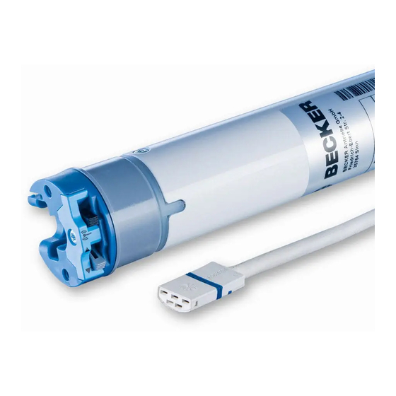
Roller shutter drive with integrated radio
transceiver
Important information for:
• Fitters / • Electricians / • Users
Please forward accordingly!
These instructions must be kept safe for future reference.
Becker-Antriebe GmbH
Friedrich-Ebert-Straße 2-4
35764 Sinn/Germany
www.becker-antriebe.com
Advertisement
Table of Contents

Related Manuals for Becker P5-B01


Summary of Contents for Becker P5-B01
- Page 1 Assembly and Operating Instructions Roller shutter drive with integrated radio transceiver Important information for: • Fitters / • Electricians / • Users Please forward accordingly! These instructions must be kept safe for future reference. Becker-Antriebe GmbH Friedrich-Ebert-Straße 2-4 35764 Sinn/Germany www.becker-antriebe.com...
-
Page 2: Table Of Contents
Table of contents General .................................... 3 Warranty ..................................... 3 Safety instructions ................................ 4 Instructions for the user.............................. 4 Instructions for installation and commissioning........................ 4 Intended use .................................. 5 Assembling and disassembling the plug-in connecting cable.................... 6 Assembling the plug-in connecting cable .......................... 6 Disassembling the plug-in connecting cable for tubular drives dia. -
Page 3: General
General These tubular drives are high-quality products with the following features: • Optimised for roller shutter operation • Can be operated with any suitable KNX transmitter • Individual, group and central radio control • No need to run wires to a switch or relay control device •... -
Page 4: Safety Instructions
Safety instructions The following safety instructions and warnings are intended to avert hazards and to prevent property damage and personal injury. Instructions for the user General information • All work, including maintenance and cleaning, on electrical installations as well as other system parts must always be performed by authorised specialists, in particular qualified electricians. -
Page 5: Intended Use
• Crushing or shearing points must be avoided or protected. • When installing the drive, all-pole disconnection from the mains with a contact gap of at least 3 mm per pole must be provided (EN 60335). • If the drive mains connecting cable is damaged, it must be replaced with the same type of mains connecting cable, which is available from the drive manufacturer. -
Page 6: Assembling And Disassembling The Plug-In Connecting Cable
Assembling and disassembling the plug-in connecting cable Assembling the plug-in connecting cable Insert the dead connecting cable into the drive head until the locating lug clicks into place in the drive. If necessary, use a suitable flathead screwdriver to assist with insertion. Set the screwdriver into one of the two plug grooves provided for this purpose. Check that the cable is properly engaged. -
Page 7: Disassembling The Plug-In Connecting Cable For Tubular Drives Dia. 35
Disassembling the plug-in connecting cable for tubular drives dia. 35. Caution Prior to disassembly, the power supply to the connecting cable must be disconnected. On drives with a diameter Ø35, insert a suitable flathead screwdriver between the locating lug and the snap-in pin, so that the snap-in pin releases the locating lug from the plug. -
Page 8: Disassembling The Plug-In Connecting Cable For Tubular Drives Dia. 45 And Dia. 58
Disassembling the plug-in connecting cable for tubular drives dia. 45 and dia. 58 Caution Prior to disassembly, the power supply to the connecting cable must be disconnected. On drives with a diameter Ø45 or Ø58, insert a suitable flathead screwdriver right into the recess of the locating latch, so that the latch releases the locating lug from the plug. -
Page 9: Undoing The Mounting Pin
Then mount the wall bracket and idler. Ensure that the barrel is aligned at right angles to the wall and that sufficient axial play is al- lowed for the mounted system. Attention When using anti-lifting devices, closed brackets must be fitted. The tubular drive presses the closed curtain down to make it difficult for people to reach under it or raise it. -
Page 10: Securing The Drive Against Axial Displacement
Securing the drive against axial displacement In order to secure the drive against axial displacement, we recommend screwing the drive adapter to the tube. -10 mm Attention When drilling into the barrel, never drill near the tubular drive! Fixing the drive adapter to the barrel dia. 35 and dia. 45 Size of drive Diameter of barrel Torque... -
Page 11: Preparation For Commissioning
After programming the transmitter, position the barrel so that the roller shutter curtain can be mounted with springs or fit the anti- lifting device in accordance with the manufacturer's instructions. When using springs/anti-lifting devices, we recommend you use at least three; for longer tubes, use three springs/anti-lifting devices per meter of barrel. -
Page 12: Checking That The Running Direction Is Correct
Readying the tubular drive for programming Readying the tubular drive for programming by switching on the power Switch on the power. ► The tubular drive is ready to program for 3 minutes Readying the tubular drive for programming with the radio switch Switch the radio switch to the inside position. -
Page 13: Limit Position Settings And Configurations
Limit position settings and configurations The commissioning (e.g. setting the limit positions etc.) and later configurations are only possible with a B-Tronic transmitter. Please find the appropriate description in the instructions for the B-Tronic transmitter. Attention When operating the tubular drive without the drive adapter for obstacle detection, if using springs a point must be set in the lower limit position. -
Page 14: Technical Data Dia. 35
Technical data dia. 35 Model P5-B01 P9-B01 Type P5/16C P9/16C PROF+ KNX PROF+ KNX Rated torque [Nm] Output speed [rpm] Limit switch range 64 revolutions Supply voltage 230 V AC / 50 Hz Connected load [W] Rated current consumption [A] 0.36... -
Page 15: What To Do If
What to do if...? Problem Cause Remedy Tubular drive is not functioning. No transmitter programmed. Program new transmitter. Transmitter is out of range of the tubular Bring transmitter within range of the tubu- drive. lar drive. Batteries in transmitter not inserted/ in- Insert batteries correctly or insert new serted incorrectly or dead. -
Page 16: Sample Wiring Diagram
Sample wiring diagram... -
Page 17: Declaration Of Conformity
Declaration of Conformity... - Page 20 2010 300 564 0 13/05/2015 ...
Need help?
Do you have a question about the P5-B01 and is the answer not in the manual?
Questions and answers