Table of Contents
Advertisement
Quick Links
Instructions
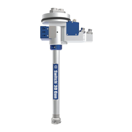
3D Gun
Swiveling applicator for robotic sealing applications. For professional use only.
Not approved for use in European explosive atmosphere locations.
See page 2 for model information.
Important Safety Instructions
Read all warnings and instructions in this
manual before using this equipment.
Save these instructions.
3A5591D
EN
Advertisement
Table of Contents

Related Manuals for Graco G-3S


Summary of Contents for Graco G-3S
- Page 1 Instructions 3D Gun 3A5591D Swiveling applicator for robotic sealing applications. For professional use only. Not approved for use in European explosive atmosphere locations. See page 2 for model information. Important Safety Instructions Read all warnings and instructions in this manual before using this equipment. Save these instructions.
-
Page 2: Table Of Contents
Nozzle Head Assembly ....11 Graco Information ......28 Cylinder Assembly . -
Page 3: Warnings
Warnings Warnings The following warnings are for the setup, use, grounding, maintenance, and repair of this equipment. The exclama- tion point symbol alerts you to a general warning and the hazard symbols refer to procedure-specific risks. When these symbols appear in the body of this manual or on warning labels, refer back to these Warnings. Product-specific hazard symbols and warnings not covered in this section may appear throughout the body of this manual where applicable. - Page 4 Warnings WARNING PRESSURIZED ALUMINUM PARTS HAZARD Use of fluids that are incompatible with aluminum in pressurized equipment can cause serious chemical reaction and equipment rupture. Failure to follow this warning can result in death, serious injury, or prop- erty damage. •...
-
Page 5: Overview
Underbody coating (UBC), Underbody Seal- ing (UBS), Liquid applied sound deadening (LASD) and seam sealing. The Graco 3D gun is designed to handle most types of single component adhesives and sealants with medium to high viscosity. The solenoid valves operating the pistons for the mate- rial valves are mounted externally for easy mainte- nance. -
Page 6: Component Identification
Component Identification Component Identification Main Assemblies Key: Central body assembly Swivel chamber Connection housing Nozzle head assembly Cylinder assembly Material valve needle Lock ring 3A5591D... -
Page 7: Central Body
Component Identification Central Body Key: Channel arrangements in the central body: Central body (with lance) Packing set material inlet Blue: Product in Packing set material return Red: Return (if unit is equipped with circulation) Gasket Green: Signals from the solenoid valves Locating pins Valve needle guide Valve needle packing set... -
Page 8: Swivel Chamber
Component Identification Swivel Chamber Swivel for one material Swivel for two different materials . 4: Swivel Chamber Key: Retaining ring Lock ring The swivel chamber supplies the material from the The compressed air is supplied through the channel at connection housing to the central body and the cylinder the rear end of the swivel chamber. -
Page 9: Connection Housing
Component Identification Connection Housing AJ AK . 5: Connection Housing Key: The connection housing is designed as the common AA Connection piece, upper platform for all external connections to the applicator. AB Screw ISO 4762 M5 x 20 AC Connection piece, lower The connections for material supply (AW) and return AD Left side cover (AV) are placed in the upper connection piece. -
Page 10: Connection Housing (Cont.)
NOTE: See your Repair-Parts manual for more informa- tion on which swivel locking bracket should be used with your applicator model. Graco provides an ABB robot arm swivel locking bracket solution. Any other robot arm requires a swivel locking bracket specific to the robot model being used. -
Page 11: Nozzle Head Assembly
Component Identification Nozzle Head Assembly Key: BA Nozzle Cap The nozzle head assembly includes two main parts: BB Nozzle Head the nozzle head (BB), and the nozzle cap (BA). The BC Spray nozzle nozzle head base part includes the valve seats for the BD Gasket material valve and mounted to the central body with BE M6 hex screw... -
Page 12: Cylinder Assembly
Component Identification Cylinder Assembly . 8: Cylinder Assembly Key: CA Packing, cylinder CB Cylinder housing CC Screw ISO 7046 M4 x 25 CD Spring CE Cylinder cover CF Screw ISO 4762 M4 x 20 CG Needle packing CH Threaded needle CJ Piston CK O-ring CL Set screw ISO 4029 M4 x 5... -
Page 13: Solenoid Valves
Component Identification Solenoid Valves Mounting Flange . 10 Key: EA Flange EB Guide pins, ISO 8734 4x10 EC Guide pin, ISO 8734 6x12 The external solenoid valves controlling the product ED M6 screws valves are easily accessible under the cover. EE Extra low head screws The mounting flange is the interface between the applicator and the sixth axis of the robot. -
Page 14: Installation
Swivel Locking Bracket Option 1: Before starting installation of the Graco 3D gun, refer to the Description on page 5 and Component Identifica- tion on page 6, in order to be familiar with the various parts of the applicator. - Page 15 Installation Before installing the spray nozzles (BC), it is important The material supply hose is connected to the connection to check that the nozzle gaskets (BD) are in their correct point “Inlet”. The material return hose is connected to positions. The nozzles must be inserted in the nozzle the connection point “Return”.
-
Page 16: Applicator Removal
Installation Applicator Removal To help prevent serious injury from pressurized fluid, relieve pressure before cleaning, checking or servic- ing the equipment. NOTE: Clean the unit and all parts surrounding it before 3. Disconnect the air hose. removing the applicator. 4. Unplug the electrical connectors by pulling the cable connectors backwards from the cable. -
Page 17: Disassembly And Reassembly Of Applicator
Disassembly and Reassembly of Applicator Disassembly and Reassembly of Applicator Applicator Disassembly 3. With the nozzle head removed from the central body, loosen the two screws and take away the lock NOTE: Ensure a proper work bench with a vice with ring and washer. - Page 18 Disassembly and Reassembly of Applicator 5. If need be, the swivel chamber and connection 7. All internal gaskets and seals should be replaced if housing can now be separated. the swivel chamber is dismantled. . 23 . 21 6. All internal parts can now be removed from the swivel chamber (special tool 17V862 recom- mended).
- Page 19 Disassembly and Reassembly of Applicator 8. The connection housing can also be further disman- tled if o-rings or sensors (if so equipped) need to be replaced. . 24 3A5591D...
- Page 20 Disassembly and Reassembly of Applicator 9. To access the material valve needles, remove the appropriate Parts manual for additional information cylinder cover, screws and springs. and special tools. . 28 . 25 13. Pick up the packings and needle guides with the 10.
-
Page 21: Applicator Assembly
Disassembly and Reassembly of Applicator Applicator Assembly 2. Mount the remaining needle packings in the cylinder housing, fit a new gasket and screw the housing to NOTE: Before assembly, make sure all spare parts are the central body. available (new in unopened package if so delivered), other parts thoroughly cleaned. - Page 22 Disassembly and Reassembly of Applicator 4. Lubricate the O-rings and the guide rings on the pis- 6. Apply light lubrication on all gaskets and O-rings tons (synthetic grease i.e. ISO Flex Topas NCA 52). prior to fitting them on the internal parts of the swivel Insert the pistons into the cylinder housing while housing.
- Page 23 Disassembly and Reassembly of Applicator 8. Carefully insert all parts into the swivel housing d. Press down the last seal. (check spare parts list for exact version). . 41 e. Cover the air holes with the mounting protector. . 37 a.
- Page 24 Disassembly and Reassembly of Applicator 9. Connect the bearing housing with the swivel hous- 12. Fit nozzles, nozzle packings and nozzle cap. ing. Note that the air distribution ring must align with the four guide pins (GP) on the bearing housing. .
-
Page 25: Parts And Wire Diagram
Parts and Wire Diagram Parts and Wire Diagram See the appropriate Parts manual for your applicator model for more information. Maintenance To help prevent serious injury from pressurized fluid, relieve pressure before cleaning, checking or servic- ing the equipment. NOTE: Before assembly, make sure all spare parts are available (new in unopened package if delivered), and other parts are thoroughly cleaned. -
Page 26: Dimensions
Dimensions Dimensions 17.4 in (442 mm) 1.1 in (28 mm) 1.5 in (38 mm) 11.9 in (302.1 mm) X = Robot Flange Dimensions 3A5591D... -
Page 27: Technical Specifications
Technical Specifications Technical Specifications 3D Gun Metric Maximum fluid working pressure 3625 psi 25 MPa, 250 bar Maximum fluid temperature 176° F 80° C Minimum air pressure requirement 80 psi 0.55 MPa, 5.5 bar Maximum air pressure 116 psi 0.8 MPa, 8 bar Length Varies by nozzle type;... -
Page 28: Graco Standard Warranty
With the exception of any special, extended, or limited warranty published by Graco, Graco will, for a period of twelve months from the date of sale, repair or replace any part of the equipment determined by Graco to be defective.
Need help?
Do you have a question about the G-3S and is the answer not in the manual?
Questions and answers