Table of Contents
Advertisement
Quick Links
Instructions - Parts
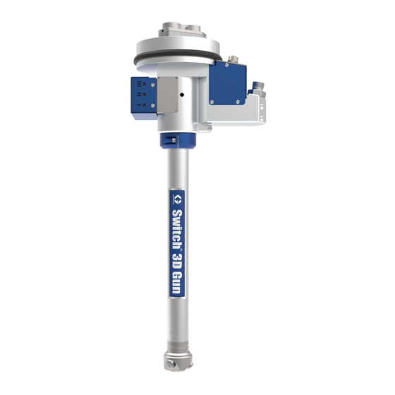
Switch
Swiveling applicator for robotic sealing applications. For professional use only.
Not approved for use in European explosive atmosphere locations.
See page 3 for model information including maximum working pressure.
Important Safety Instructions
Read all warnings and instructions in this
manual before using the equipment.
Save these instructions.
Model Number
17V558
™
3D Gun
Model Number
17V562
Model Number
17V567
3A8004B
EN
Advertisement
Table of Contents

Related Manuals for Graco Switch 3D Gun


Summary of Contents for Graco Switch 3D Gun
- Page 1 Instructions - Parts ™ Switch 3D Gun 3A8004B Swiveling applicator for robotic sealing applications. For professional use only. Not approved for use in European explosive atmosphere locations. See page 3 for model information including maximum working pressure. Important Safety Instructions Read all warnings and instructions in this manual before using the equipment.
-
Page 2: Table Of Contents
Pattern Width Versus Tip Sizes ... . . 35 Flush the Switch 3D Gun ....11 Material Pressure Versus Tip Sizes . -
Page 3: Models
Models Models Maximum Working Part No. Series Pressure Material Port Options Sensor Types Cable Type psi (MPa, bar) Two Port One Material With 17V558 3350(23.1,231) No Sensors 5 Pin Recirculation Two Port One Material With 17V559 3350(23.1,231) Temperature 18 Pin Recirculation Two Port One Material With 17V561... -
Page 4: Warnings
Warnings Warnings The following warnings are for the setup, use, grounding, maintenance, and repair of this equipment. The exclamation point symbol alerts you to a general warning and the hazard symbols refer to procedure-specific risks. When these symbols appear in the body of this manual or on warning labels, refer back to these Warnings. Product-specific hazard symbols and warnings not covered in this section may appear throughout the body of this manual where applicable. - Page 5 Warnings WARNING PRESSURIZED ALUMINUM PARTS HAZARD Use of fluids that are incompatible with aluminum in pressurized equipment can cause serious chemical reaction and equipment rupture. Failure to follow this warning can result in death, serious injury, or property damage. • Do not use 1,1,1-trichloroethane, methylene chloride, other halogenated hydrocarbon solvents or fluids containing such solvents.
-
Page 6: Overview
The solenoid valves operating the pistons for the robotic applications that requires high precision and material valves are mounted externally for easy quality. The Switch 3D Gun is equipped with a swivel for maintenance. optimum robot flexibility and has three individually operated nozzles. -
Page 7: Component Identification
Component Identification Component Identification Main Assembly Key: A. Nozzle Head Assembly B. Lock Ring Assembly C. Central Body Assembly D. Connection Housing (two inlet shown) E. Swivel Chamber F. Rod Shutoff Valve and Cylinder Assembly 3A8004B... -
Page 8: Installation
To maintain grounding continuity when flushing or relieving pressure: hold metal part of the Switch 3D To ensure trouble free operation of the Switch 3D Gun, Gun firmly to the inside of a grounded metal pail, then it is important that the unit is properly installed on the trigger the valves. - Page 9 6mm guide pins Anti-Rotation Brackets After the Switch 3D Gun is mounted to the robot, the anti-rotation brackets must be attached to the swivel housing (619) and to the fixation point on the robot using the hex head screws. Exact fitting of the anti-rotation brackets will depend on the robot and kit being used.
- Page 10 NOTICE After the Switch 3D Gun is completely installed on the robot, the Switch 3D Gun can be tested for leaks. This Only use air fittings that are rated at a temperature procedure also primes the Switch 3D Gun for use.
-
Page 11: Operation
Operation Flush the Switch 3D Gun Operation Overview The Switch 3D gun dispenses ribbons of material onto a To avoid fire and explosion, always ground equipment substrate. The height and width of the material bead is and waste container. To avoid static sparking and... -
Page 12: Maintenance
Maintenance Maintenance Preventive Maintenance Typical wear parts in the Switch 3D Gun are the sealing rings inside the swivel chamber, the rod shutoff valves, To help prevent serious injury from pressurized fluid, rod seals and the rod shutoff valve seats. -
Page 13: Factors Affecting Switch 3D Gun Life
Life The maintenance tables should be used as a guideline for the frequency of maintenance tasks. Additional fac- tors that could affect Switch 3D Gun life include the fol- lowing: • Material Fluid - Abrasive or fiber filled fluids are much harder on seals, shafts, and seats than non-abrasive fluids such as oil. -
Page 14: Troubleshooting
Troubleshooting Troubleshooting 1. Follow Pressure Relief Procedure, page 11, before checking or repairing the Switch 3D Gun. Problem Cause Solution Air leaks from Switch 3D Gun. Worn gasket. Replace gasket. Loose or worn air connections. Tighten air connections. Worn o-rings. -
Page 15: Repair
Follow the Flush the Switch 3D Gun page 11. b. Follow the Pressure Relief Procedure page 2. Disconnect the material inlet hose and the material 7. The Switch 3D Gun can be now be removed from return hose. Always use two wrenches when the robot. - Page 16 Repair 305/306 . 11 4. Unscrew the three M4 hex head screws (304) that 2. To access the shutoff valve rods (512) and pistons attaches the nozzle head (301) and adapter (506), first evenly remove the three M4 screws (104/105) to the front end of the central body (101). (501).
- Page 17 Repair . 13 6. Remove the three M4 screws (508) securing the air . 15 cylinder housing (509). After the air cylinder housing 8. With the adapter removed from the central body, is removed the cylinder housing gasket (511) and loosen the two M5 screws (403) and remove the the rod seals (201) can be removed.
- Page 18 Repair 9. Slide off the swivel chamber assembly with connection housing. See F . 17. Swivel chamber assembly with connection housing . 17 10. The internals of the connection housing assembly can be accessed by the following: . 18 a. Remove the top cover (707) by removing the two M3 cover screws (705).
- Page 19 Repair 11. All internal parts and seals can now be removed from the swivel housing (619). All internal gaskets and seals should be replaced if the swivel chamber is dismantled. See F . 19. . 19 12. The solenoid valves and manifold can be accessed by removing the cover (612) and removing the four M3 screws (611).
-
Page 20: Switch 3D Gun Assembly
Repair Switch 3D Gun Assembly NOTE: Before assembly, make sure all spare parts are available and other parts thoroughly cleaned. Suitable lubricant and thread locking compound should also be available. 1. Apply a light lubricant on all gaskets and O-rings prior to fitting them on the internal parts of the swivel housing. - Page 21 Repair 57.5 in-lbs (6.5 N•m). Cover plate (707) is then 6. Insert the inlet packing spacers, (203) and return attached with two M3 screws (705). Torque to 12 packing spacer (204) rod seals (201) and rod in-lbs (1.35 N•m). Used O-Rings (722) should be bearings (202) into the central body.
- Page 22 Repair material adapter (103) or gasket (106) for one a. Lubricate the O-rings (505) and the guide rings material adapter (105). See F . 28 (504) using a synthetic grease. b. Place rings onto the pistons and make sure they are seated securely in their correct grooves.
-
Page 23: Testing Before Installation
Repair . 32 Testing Before Installation If the Switch 3D Gun has been assembled after a major repair or maintenance operation, it is recommended to perform a function test before the Switch 3D Gun is returned to production. A minimum level of function test is to connect the compressed air supply and check for air leakage by opening each of the solenoid valves (613) manually. -
Page 24: Parts
Parts Parts Parts Key . 33 Key: A. Nozzle Head Assembly page No. 26 B. Lock Ring Assembly page No. 26 C Central Body Assembly page No. 25 D.Connection Housing (two inlet shown) page No. 29 E. Swivel Chamber page No. 28 F. -
Page 25: Central Body Assembly
Parts Central Body Assembly Central Body Assembly Parts List Quantity Per Model Number Ref. Part Description 25T656 BODY, central 102* 17V839 GASKET, adapter 17V856 ADAPTER, two material 104* 18C660 GASKET, lower, two material 18C662 ADAPTER, one material 106* 18C715 GASKET, lower, one material Ref. -
Page 26: Nozzle Head Assembly
Parts Nozzle Head Assembly Lock Ring Assembly Lock Ring Parts List 305/306 Ref. Part Description Qty. Nozzle Head Parts List 401* 17V910 RING, lock assembly 17V817 WASHER Ref. Part Description Qty. 117026 SCREW, M5x12, SHCS 17V875 HEAD, nozzle --------- NOZZLE (reference) * Assembly 17V910 includes parts 17V817 and 117026. -
Page 27: Rod Shutoff Valve And Cylinder Assembly
Parts Rod Shutoff Valve and Cylinder Assembly Rod Shutoff Valve and Cylinder Assembly Parts List Ref. Part Description Qty. 116474 SCREW, M4x20, SHCS 17V818 COVER, cylinder 17V830 SPRING 17V832 RING, guide 17V812 O-RING 17V826 PISTON 129647 SCREW, M4x5, SHSS 132979 SCREW, M4x30, FHMS 509* 25T486 HOUSING, air, cylinder 17V813 SEAL, rod... -
Page 28: Swivel Chamber
Parts Swivel Chamber Central Body Assembly Parts List Ref. Part Description Qty. Ref. Part Description Qty. 132555 SCREW, M3x6, FHMS 17V804 SCREW, M5x16, FHMS 17V889 COVER, inner 17V828 BEARING, flange 17V887 GASKET, manifold 17V893 RING, seal, hr 25T490 HOUSING, swivel 17V901 HOUSING, bearing 17V816 FITTING, elbow, swivel 605*... -
Page 29: Connection Housing
Parts Connection Housing 724/725 3A8004B... - Page 30 Parts Connection Housing Parts List Quantity Per Model Number Ref. Part Description 17V803 SCREW, M5x30, SCHS 17V902 ADAPTER, dual inlet 17V809 SEAL, washer, 16MM 17V916 FITTING, nipple,3/8 BSPP 132559 SCREW, M3x6, BHCS 17V843 COVER, side, blue 17V844 COVER, top, blue 16G740 SCREW, M3x8, SCHS 17V897 CONNECTOR, T3 132554 SPACER, nylon, M3, 6MM, OD 3MM HT...
-
Page 31: Kits And Tools
0.31 (8) 17V670 0.012 (0.30) NOTE: Service Kit 25t484 is provided for preventive 0.35 (9) 17V671 0.012 (0.30) maintenance done on the Switch 3D Gun once a year 0.39 (10) 17V672 0.012 (0.30) based on average usage. 0.31 (8) 17V673 0.015 (0.38) -
Page 32: Air Cylinder Housing Service Kit, 25T486
Kits and Tools Air Cylinder Housing Service Valve Shaft Service Kit Parts List, 25T487 Kit, 25T486 Ref. Part Description Qty. 17V813 SEAL, rod 17V838 ROD, shutoff, valve 17V831 BEARING, rod Bearing Seals Kit, 25T488 Air Cylinder Housing Service Kit Parts List, 25T486 Valve Shaft Service Kit Parts List, 25T488 Ref. -
Page 33: Pin Cable Kit, 17V857
Kits and Tools 5 Pin Cable Kit, 17V857 Seal Insert and Removal Tool instructions Seal Removal 1001 To remove a rod seal, place pointed end of the seal installation rod (902) through the center of the rod seal (201). Hook the indent of the tool onto the opposite face of the seal and retract seal from the packing spacers (203 and 204) or air cylinder housing (509). -
Page 34: Mounting Tool, 17V972
Kits and Tools Mounting Tool, 17V972 1100 Mounting Tool Part List, 17V972 Ref. Part Description Qty. 1100 17V972 TOOL, mounting Tool Kit, 17V859 1200 Tool Kit , 17V859 Ref. Part Description Qty. 1200 17V859 TOOL, Kit 3A8004B... -
Page 35: Performance Charts
Performance Charts Performance Charts Pattern Width Versus Tip Sizes The following tests were performed using a typical PVC seam sealer. See F . 36. • 600,000 centipose • Specific gravity 0.82 The graph below shows a fixed flow rate of 9.4 cc / sec and a fixed robot speed of 300 mm / sec. -
Page 36: Material Pressure Versus Tip Sizes
Performance Charts Material Pressure Versus Tip Sizes The graph below represents the pressures for each tip to achieve the width shown in the Pattern Width Versus Tip Sizes graph. See F . 36. Pressure data may be useful when choosing a tip size due to the pressure limitation of the metering equipment. -
Page 37: Pattern Height / Width Versus Cc/Sec
Performance Charts Pattern Height / Width Versus cc/sec Increasing the flow rate at the same robot speed will increase the width of the pattern and bead height. See F . 38 Pattern Height / width Versus cc/sec 14.1 cc/sec 11.8 cc/sec 9.4 cc/sec Width 17V676 Nozzle... -
Page 38: Dimensions
Dimensions Dimensions 5.9 in 149.6 mm 4.5 in OD 11.5 mm 2.4 in 61.6 mm 12.125 in 308 mm 1.5 in 1.1 in 38 mm 28 mm 17.75 in 451mm . 40 Side View Typical for 17V558, 17V559, 17V561, 17V562, 17V563 4.7 in 120.0 mm 4.5 in OD... - Page 39 Dimensions 120° 4 mm dia. 4.05 mm dia. +/- 0.03 2 Holes on 105 mm dia. BC 40° 4.45 in dia. 113 mm M6 THRU 3 Holes EQ SP on 103 mm dia. BC . 42 Robot Mounting Flange Typical for all Switch 3D Guns 3A8004B...
-
Page 40: Wiring Diagrams
Wiring Diagrams Wiring Diagrams 5 Pin - No Sensor for 17V558, 17V562 and 17V564 5 pin connector T2 connector 5 Pin Connector Pin No. Description Solenoid No.1 Signal solenoid solenoid Solenoid No. 2 Signal solenoid Solenoid No. 3 Signal Common ---------- WIRING DIAGRAM SOLENOID WIRING SCHEMATIC... -
Page 41: Pin Connections For Temperature And Pressure
Wiring Diagrams 18 Pin Connections for Temperature and Pressure Sensors. Model No. 17V559, 17V561, 17V565 and 17V567 Pressure Sensor Connector, 18 See Note. Temperature Sensor See Note. T3 connector Solenoid Solenoid Solenoid WIRING DIAGRAM SOLENOID WIRING SCHEMATIC Temp. Inlet 1 Press. -
Page 42: 18 Pin - 2 Temperature Sensors For 17V563
Wiring Diagrams 18 Pin - 2 Temperature Sensors for 17V563 Connector, 18 Temp. Inlet 1 Temp. Inlet 2 T3 connector Solenoid Solenoid Solenoid SOLENOID WIRING SCHEMATIC WIRING DIAGRAM Temp. Inlet 1 Temp. Inlet 2 SENSOR WIRING SCHEMATIC . 45 Schematic for 17V563 NOTE: See Electrical Components page 45 for specifications. -
Page 43: 18 Pin Connector
Wiring Diagrams 18 Pin Connector 5 Pin Cable Schematic Pin No. Wire Color Brown White . 46 Blue Black Grey Lemo 18 Terminal Terminal 2 Wire Color 18 Pin Cable Schematic Pin No. Wire Color Pin No. Wire Color White Purple Brown Grey/Pink... -
Page 44: Technical Specifications
Technical Specifications Technical Specifications Switch 3D Gun Metric Maximum fluid working pressure 3350 psi 23.1 MPa, 231 bar Maximum fluid temperature 176° F 80° C Minimum air pressure 80 psi 0.55 MPa, 5.5 bar 0.8 MPa, 8bar Maximum air pressure... -
Page 45: California Proposition 65
Technical Specifications Electrical Components Part Number Description Electrical Rating Sensor, Temperature 100 ohm platinum rtd sensor 17V829 Transducer (350 bar, 5000 psi) 24 Vdc input, 0.5 to 4.5 Vdc output 17X657 Solenoid 24 Vdc: 2.88W 17V890 California Proposition 65 CALIFORNIA RESIDENTS WARNING: Cancer and reproductive harm –... -
Page 46: Graco Standard Warranty
With the exception of any special, extended, or limited warranty published by Graco, Graco will, for a period of twelve months from the date of sale, repair or replace any part of the equipment determined by Graco to be defective.
Need help?
Do you have a question about the Switch 3D Gun and is the answer not in the manual?
Questions and answers