Table of Contents
Advertisement
Quick Links
Instructions - Parts
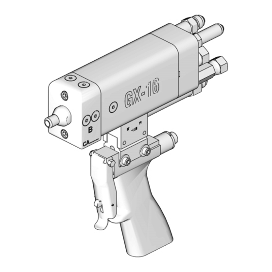
GX-16
For dispensing polyol and isocyanate materials only. For professional use only.
For indoor use only. Not approved for use in European explosive atmosphere
requirements.
3000 psi (21 MPa, 207 bar) Maximum Fluid Working Pressure
2500 psi (17 MPa, 172 bar) Maximum Hydraulic Working Pressure
180°F (82°C) Maximum Fluid Temperature
Important Safety Instructions
Read all warnings and instructions in this
manual. Save these instructions.
Model 257496 shown
313536U
EN
ti12896a
Advertisement
Table of Contents

Related Manuals for Graco GX-16


Summary of Contents for Graco GX-16
- Page 1 Instructions - Parts GX-16 313536U For dispensing polyol and isocyanate materials only. For professional use only. For indoor use only. Not approved for use in European explosive atmosphere requirements. 3000 psi (21 MPa, 207 bar) Maximum Fluid Working Pressure 2500 psi (17 MPa, 172 bar) Maximum Hydraulic Working Pressure 180°F (82°C) Maximum Fluid Temperature...
-
Page 2: Table Of Contents
Moisture Sensitivity of Isocyanates ... 7 Graco Information ......42 Foam Resins with 245 fa Blowing Agents . -
Page 3: Models
GX-16 Pour Gun, 24:1, Pour Handle, Left Side Chemical Tubes, Star-Shaped Trigger Switch Connector 257494† GX-16 Pour Gun, 24:1, Pour Handle, Right Side Chemical Tubes, Cir- cular Trigger Switch Connector 257495† GX-16 Pour Gun, 24:1, Pour Handle, Left Side Chemical Tubes, Cir- cular Trigger Switch Connector 257496†... -
Page 4: Warnings
Warnings Warnings The following warnings are for the setup, use, grounding, maintenance, and repair of this equipment. The exclama- tion point symbol alerts you to a general warning and the hazard symbol refers to procedure-specific risk. Refer back to these warnings. Additional, product-specific warnings may be found throughout the body of this manual where applicable. - Page 5 Warnings WARNING EQUIPMENT MISUSE HAZARD Misuse can cause death or serious injury. • Do not operate the unit when fatigued or under the influence of drugs or alcohol. • Do not exceed the maximum working pressure or temperature rating of the lowest rated system component. See Technical Data in all equipment manuals.
-
Page 6: Isocyanate Conditions
Important Two-Component Material Information Important Two-Component Material Information Isocyanate Conditions Spraying or dispensing fluids that contain isocyanates creates potentially harmful mists, vapors, and atomized particulates. • Read and understand the fluid manufacturer’s warnings and Safety Data Sheet (SDS) to know specific haz- ards and precautions related to isocyanates. -
Page 7: For All Applications Except Spray Foam
Important Two-Component Material Information For all applications except spray Keep Components A and B foam Separate Cross-contamination can result in cured material in fluid Spraying or dispensing fluids that contain isocyanates cre- lines which could cause serious injury or damage equip- ates potentially harmful mists, vapors, and atomized partic- ment. -
Page 8: Foam Resins With 245 Fa Blowing Agents
Grounding Grounding Foam Resins with 245 fa Blowing Agents Some foam blowing agents will froth at temperatures above 90°F (33°C) when not under pressure, especially if agitated. To reduce frothing, minimize preheating in a circulation sys- tem. The equipment must be grounded. Grounding reduces the risk of static and electric shock by providing an Changing Materials escape wire for the electrical current due to static build... -
Page 9: Trigger Lock
Trigger Lock Trigger Lock Verify that the trigger lock is engaged whenever you stop pouring to avoid accidental triggering. Check daily for chemical build-up on trigger, trigger lock, and trigger lock spring that can prevent proper trigger lock function. Engage To engage the trigger lock, release the trigger. -
Page 10: Setup
Setup Setup Gun Connections ti12897a Description Tape Color † Fitting Size HFR Systems Only 7/16 ORG x 7/16 ORG x A Pressure Line #6 JIC Female #5 JIC Female 7/16 ORG x 7/16 ORG x A Return Line Red and White #6 JIC Male #5 JIC Male 7/16 ORG x... -
Page 11: Fluid Line
Setup Fluid Line NOTE: Pressure should not increase while air is purged from hoses. Fluid Filter: Use a 25 micron stainless steel element to 5. Turn off power pack. Verify no pressure exists in filter particles from the fluid as it leaves the pump. hoses. -
Page 12: Shutoff Valve Setup
Mounting 11. Install chemical hoses to gun. See F . 5 on page 10 and F . 9. Use the following mounting dimensions to mount the GX-16 gun body. ti18184a ti14493a A Width: 1.125 in. (28.58 mm) Shutoff Valve Setup B Diameter: 0.159 in. -
Page 13: Startup
Startup Startup 1. If your setup uses the optional shutoff valves, 4. Close dump valve on hydraulic power pack. rotate the handles to the “open” position. Open Position Closed Position Hydraulic pressure must not exceed the maximum working pressure of 2500 psi (17 MPa, 172 bar). 5. -
Page 14: Operation
Operation Operation Theory of Operation Circulation Dispense Key: Key: A Pressure Line A Return Line A Pressure Line B Return Line A Return Line B Pressure Line B Return Line Hydraulic Open Line B Pressure Line Hydraulic Close Line Hydraulic Open Line Piston Rod Hydraulic Close Line Hydraulic Piston... -
Page 15: Pressure Relief Procedure
Pressure Relief Procedure Pressure Relief Shutdown Procedure 1. Perform Pressure Relief Procedure. 2. Perform any required maintenance. See Mainte- 1. If your setup uses the optional shutoff valves, nance on page 16. rotate the handles to the “open” position. 3. If system will not be in use for longer than two 2. -
Page 16: Maintenance
Before using any other type of oil in this motor, con- 1. Perform pressure relief procedure. See Pressure tact your Graco distributor. Unauthorized use of Relief Procedure on page 15. lesser grade oil or substitutes may void the war- ranty. -
Page 17: Clean And Service The Orifices And Filters
Maintenance Clean and Service the Orifices 2. If your setup uses the optional shutoff valves, rotate the handles to the “close” position. and Filters 3. Use a 7/16 in. wrench to remove the orifice. 4. Use a 1/8 in. allen key to remove the cleanout plug next to the orifice. -
Page 18: Proximity Switch Replacement Procedure
Maintenance Proximity Switch Replacement Procedure 1. Perform pressure relief procedure. See Pressure Relief Procedure on page 15. 2. Remove proximity switch cable attached to proxim- ity switch. 3. Remove proximity switch from rear of gun body. ti12897a . 18 4. Install new proximity switch. 5. -
Page 19: Troubleshooting
Faulty proximity switch Replace proximity switch Damaged piston u-cup seals Send gun to Graco for repair Chemical crossover Seal failure on piston rod Send gun to Graco for repair Hydraulic leak into divorce chamber... -
Page 20: Parts
101a, c 101b, d ti12900a Model 257496 shown Quantity by Model Ref. Part Description 257496 257498 257499 257505 257506 257507 24J187 24E876 DISPENSER, GX-16, 1:1, 257513 pre-assy DISPENSER, GX-16, 24:1, 257514 pre-assy DISPENSER, GX-16, rev 257515 block, pre-assy . PLUG, sae02, socket head, . - Page 21 Quantity by Model Ref. Part Description 257496 257498 257499 257505 257506 257507 24J187 24E876 . 101d . 122679 . O-RING, epr, #902 257509 HANDLE, GX-16, pistol grip HANDLE, GX-16, pistol grip, 257510 isolated 122694 SCREW, bhsc, 10-32x1.00, ms O-RING, fluoroelastomer,...
-
Page 22: Gun Models 257492, 257493, 257494, 257495
Parts Gun Models 257492, 257493, 257494, 257495 216 215 201a, c 201b, d ti12901a Model 257492 shown 313536U... - Page 23 257493 257494 257495 Ref. Part Description 257514 DISPENSER, GX-16, 24:1, pre-assy . 201a . 122685 . PLUG, sae02, socket head, m, ms, 6k . 201b . 261500 . O-RING, #902, fluoroelastomer . 201c . 122687 . PLUG, sae02, 316 ss .
-
Page 24: Gun Models 257497, 257502, 257503, 257504, 24E877, 24E878
Quantity by Model Ref. Part Description 257497 257502 257503 257504 24E877 24E878 257513 DISPENSER, GX-16, 1:1, pre-assy 257514 DISPENSER, GX-16, 24:1, pre-assy . 122685 . PLUG, sae02, socket head, m, ms, . 301a . 301b . 261500 . O-RING, #902, fluoroelastomer . - Page 25 Parts Quantity by Model Ref. Part Description 257497 257502 257503 257504 24E877 24E878 257701 RESTRICTOR, orifice assy, 0.011 257717 RESTRICTOR, orifice assy, 0.039 168518 PACKING, o-ring, fluoroelastomer 285967 O-RING, #006 epr 168518 PACKING, o-ring, fluoroelastomer 261500 O-RING, #902, fluoroelastomer 122679 O-RING, epr, #902 261500 O-RING, #902, fluoroelastomer 122707 O-RING, fluoroelastomer, #904, 75a 122714 O-RING, fluoroelastomer, #904, 75a...
-
Page 26: Gun Models 24K233, 24K234
Parts Gun Models 24K233, 24K234 ti17784a Model 24K233 shown 313536U... - Page 27 Parts Quantity Ref. Part Description 24K233 24K234 257514 DISPENSER, GX-16, 24:1, pre-assy 122714 O-RING, fluoroelastomer, #904, 75a 122707 O-RING, fluoroelastomer, #904, 75a 122720 ADAPTER, jic06xsae04, mm, ms, 6k, fluoroelastomer 122717 ADAPTER, swivel, jic06xsae04, fm, ms, 6k 122710 ADAPTER, jic05xsae04, mm, ss, 6k...
-
Page 28: Dispenser Models 257513, 257514, 257515
Parts Dispenser Models 257513, 257514, 257515 r_257515_parts Model 257515 shown 313536U... - Page 29 Parts Quantity Ref. Part Description 257513 257514 257515 295229 FITTING, grease, 1/4-28 295693 PLUG, pipe 122687 PLUG, sae02, 316 ss 122685 PLUG, sae02, skt hd, ms, 6k 261500 O-RING, #902 122679 O-RING, #902 122687 PLUG, sae02, 316 ss 122685 PLUG, sae02, skt hd, ms, 6k 122679 O-RING, #902 261500...
-
Page 30: Gun Models 26C466, 25E973, 25E974, 25E975
Parts Gun Models 26C466, 25E973, 25E974, 25E975 615a 615b 601a,c 601b,d 601e 618b 618a 313536U... - Page 31 26C464 magnet BLOCK, gx-16, chamber, 601e 25E971 non-magnet BLOCK, gx-16, chamber, 257511 plain KIT, handle, gx-16, hfr, nvh, 26C463 122714 O-RING, ep 122707 O-RING, fkm 15Y177 FITTING 122711 FITTING, elbow 122713 SWITCH, prox 122709 ADAPTER, swivel 122710 ADAPTER RESTRICTOR, orifice 257712 assembly, .029...
-
Page 32: Orifices
Parts Orifices Part Orifice Assembly Size 257700 Orifice Plug 257701 0.011 in. 257702 0.013 in. 257703 0.016 in. 257704 0.018 in. 257705 0.020 in. 257706 0.022 in. 257707 0.023 in. 257708 0.024 in. 257709 0.025 in. 257710 0.026 in. 257711 0.028 in. -
Page 33: Gun Handle Kit 24K223
Gun Handle Kit 24K223 ti17785a Ref. Part Description 24D073 KIT, handle, EP 16H435 ISOLATOR, handle, GX-16 to MD2 16H436 ISOLATOR, handle, GX-16 to MD2, left 16H437 ISOLATOR, handle, GX-16 to MD2, right 122694 SCREW, button head 121070 SCREW, machine 313536U... -
Page 34: Gun Handle Models 257509, 257510
Parts Gun Handle Models 257509, 257510 ti13383a Model 257510 shown Ref. Part Description 257576 HANDLE 112095 SCREW, set 257578 SWITCH, trigger 299650 SPRING 257577 PLUNGER, spring 15Y159 NUT, retainer 257579 TRIGGER, safety, gun 295671 SCREW, mounting, trigger 295438 NUT, stop, elastic, 5-40 15Y160 ISOLATOR, handle (Model 257510 only) -
Page 35: Gun Handle Model 26C463
PLUNGER, trigger, 2K handle 551396 SPRING, .26 x .37 x .51 music wire 16H435 ISOLATOR, handle, GX-16 to MD2 16H436 ISOLATOR, handle, GX-16 to MD2, left 16H437 ISOLATOR, handle, GX-16 to MD2, right 122694 SCREW, bhsc, 10 x 1.00, ms 121070 SCREW, machine, #8 x 1.375... - Page 36 Parts LED Trigger for HFR-NVH a. Not Ready (Dark or OFF) - This will occur when not in a dispense mode (disable or night The HFR setup Advanced #7 screen contains the fol- modes), the user is on a setup screen when lowing control options for gun handle 26C463: idle, an alarm is active, the system is in low pressure recirculation mode or not moving (full...
-
Page 37: Pour Handle Models 257594, 257596
Parts Pour Handle Models 257594, 257596 1002 1001 1008 1009 1002 1004 1007 1010 1005 1006 Model 257594 shown 1003 ti14499a Ref. Part Description 1001 295438 NUT, stop, elastic, 5-40 1002 122746 SCREW, shc, 10-32x.375, ms, nyloc 1003 257595 CONTROL, circular connector/led (assembly 257594 only) 257597 CONTROL, star-shaped connector/led... -
Page 38: Optional Shutoff Valve Kit
24L498, KIT, 24M596, KIT, valve shutoff, valve shutoff, Ref. Part Description GX-16 GX-16, NVH 1101 --- VALVE, ball, 2 way, 1/4 NPT, female 1102 --- ADAPTER, 1/2-20 JIC x 1/4 NPT ADAPTER, JIC08x1/4, MS 1103 --- ADAPTER, JIC06x1/4, SS 1104 ---... -
Page 39: Accessories
Accessories Accessories Description Part Hose Kit 24C999 Gun Cover, straight fittings 123694 Gun Cover, 90 deg. fittings 124226 Hose Cover, 12 ft 123698 Right Fitting Adapter Kit 24K672 Left Fitting Adapter Kit 24K674 Grease Fitting Flush Kit 24T326 313536U... -
Page 40: Important Two-Component Material Information . 6 Dimensions
Accessories Dimensions ti12896a Model 257496 shown Dimension Model 257492, 257493, 15.1 (383) 9.6 (244) 7.9 (201) 257494, 257495 257497, 257502, 257503, 257504, 24E877, 24E878, 10.3 (262) 3.6 (91) 3.7 (94) 24K233, 24K234 (no hoses) 257496, 257507, 9.3 (236) 3.0 (76) 8.9 (226) 26C466, 25E975 257505, 257506... -
Page 41: Technical Data
Technical Data Technical Data Maximum Fluid Working Pressure ....3000 psi (21 MPa, 207 bar) Maximum Hydraulic Working Pressure ....2500 psi (17 MPa, 172 bar) Maximum Fluid Temperature . -
Page 42: Graco Standard Warranty
With the exception of any special, extended, or limited warranty published by Graco, Graco will, for a period of twelve months from the date of sale, repair or replace any part of the equipment determined by Graco to be defective.
Need help?
Do you have a question about the GX-16 and is the answer not in the manual?
Questions and answers