
Related Manuals for Sports Attack STRIKE ATTACK


Summary of Contents for Sports Attack STRIKE ATTACK
- Page 1 SOCCER MACHINE STRIKE ATTACK™ SOCCER MACHINE PATENTS APPLIED FOR INSTRUCTION MANUAL OPERATION · SETUP · USE & CARE · SERVICE SPORTS ATTACK LLC. | 800.717.4251 | www.sportsattack.com...
- Page 2 To return an item, please If a service person is needed, Sports Attack will pay the pre-approved labor charge to get contact our Customer Service your machine back in working order.
-
Page 3: Table Of Contents
This manual contains the information needed to properly setup the Strike Attack, and to use, care for and maintain it in a manner which will ensure its optimum performance. -
Page 4: Safety Instructions
ALWAYS set the speed control to “0” before connecting the machine to power. Check that the speed control is at “0” before turning the throwing wheels “ON”. Do not allow anyone to walk in front of the Strike Attack if it is connected to electrical power. Do not allow anyone to walk in front of the Strike Attack if it is on. CAUTION: DO NOT plug in or energize this equipment until all assembly instructions and operation instructions are read and followed. -
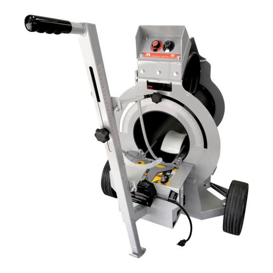
Page 5: Component View
Wheel Guard INFORMATION If you have any questions regarding the safe operation of Motor this equipment, please call: Sports Attack Customer Service: 800.717.4251 or 775.345.2882 • To reorder components, a parts list and part numbers can be found on page 14. -
Page 6: Set-Up & Preparation
SET-UP & PREPARATION SAFETY HINT When lowering or lifting the SETTING UP THE STRIKE ATTACK (for both AC and battery models) Strike Attack, keep your back 1. Tilt the machine forward until it is lying face down. Remove locking pin A straight and lift using your legs. - Page 7 ADDITIONAL (CONT’D) INFORMATION If you have any questions regarding the safe operation of this equipment, please call: Sports Attack Customer Service: 800.717.4251 or 775-345.2882 • To reorder components, a parts list and part numbers can be found on page 14.
- Page 8 14. Figure 6 Attach battery wires. Figure 7 Stand Strike Attack upright. S T R I K E AT TAC K™ S O C C E R M AC H I N E S P O RT S AT TAC K , L LC •...
-
Page 9: Generator Information
No lights - Indicates AC power is applied to the charger F ull Line of Green lights - Indicates when the batter is fully charged The charger on the Strike Attack does not damage fully charged batteries left connected to it. You may also charge the battery using any manufactured automotive battery charger. - Page 10 1. Unplug charger from power source. this equipment, please call: 2. Turn both speed control knobs to “0.” Make sure throwing wheels are stopped. Sports Attack Customer Service: 3. Unplug battery connector from throwing head. See A 800.717.4251 or 775.345.2882 4. Loosen and remove two wing nuts on battery terminal connectors. Remove the two wires on each terminal (1 wire from charger and 1 wire from battery harness).
-
Page 11: Care, Cleaning & Maintenance
For wheels with excessive build-up, you may need to repeat this process. EXAMINE THE MACHINE Examine Strike Attack for condition and completeness before every use: 1. Throwing wheels must be tight on the motor shafts. Check that the four bolts holding each motor to the throwing head assembly are tight. -
Page 12: Component Replacement
COMPONENT REPLACEMENT THROWING WHEEL REPLACEMENT 1. Turn both throwing wheel control knobs to “0.” If an AC unit, unplug the power cord. Remove the 4 bolts on the outside wheel guard. 2. Hold the wheel so that it cannot move. Turn the keyway retaining bolt counter-clockwise using a half inch box-end wrench (See Figure 9). Suggestion: If the bolt is too tight, give the opposite end of the wrench a series of light taps with a hammer making sure the wrench remains on the bolt. - Page 13 COMPONENT REPLACEMENT (CONT’D) MOTOR REPLACEMENT TOOLS MOTOR REPLACEMENT ” wrench 1. Turn the speed control knobs to “0.” If an AC unit, unplug the power cord. ” wrench 2. Remove outside wheel guard. 3. Remove the throwing wheel (See page 10). 4. Remove inside wheel guard. 5. Unbolt 4 bolts (See Figure 10) and slide motor out. Reassemble with new motor in reverse order.
- Page 14 COMPONENT REPLACEMENT (CONT’D) AC MODEL CONTROLLER REPLACEMENT 1. Turn the power switch “OFF” and unplug the power cord. 2. Remove knob from the controller. 3. Remove four screws holding controller faceplate into main casting. Note the position of the main power and motor wires on the controller, then disconnect the wires. See Figure 12 for the two motor wires.
- Page 15 WIRING COMPONENT REPLACEMENT (CONT’D) DC MODEL CONTROLLER REPLACEMENT POWER CORD White or Blue Wire (1) 1. Turn the power switch “OFF” and unplug the power cord. To middle male terminal marked “N.” 2. Remove knob from the controller. Black or Brown Wire (2) 3. Remove four screws holding controller faceplate into main casting. Note the To circuit breaker.
-
Page 16: Exploded View
EXPLODED VIEW Transport Wheel Assy Base FRONT Assy Base REAR Controller Assy Handle Assy (AC model shown) 6 Motor-Side Wheel Guard 7 Wheel Guard Throwing Wheel Motor Motor Mount Plate (Orange) Elevation/Rotation Knob Control Knobs 13 Plastic Handle Grip Wheel, Tube Rotation S T R I K E AT TAC K™ S O C C E R M AC H I N E S P O RT S AT TAC K , L LC •... -
Page 17: Parts List
PARTS LIST o order additional parts, please contact: REF#s PART NO. DESCRIPTION Sports Attack Customer Service Dept. 281-0001 Travel Wheel 800.717.4251 533-6008 775.345.2883 Assembly Base FRONT 533-6009 Assembly Base REAR 520-0073 Controller Assembly 553-6014 AC Handle Assembly (shown) 533-6013 DC Handle Assembly...
Need help?
Do you have a question about the STRIKE ATTACK and is the answer not in the manual?
Questions and answers