Table of Contents
Advertisement
Quick Links
INSTRUCTIONS FOR INSTALLATION, OPERATION, AND MAINTENANCE
Understand manual before use. Operation of this device without understanding the manual and
DANGER
receiving proper training is a misuse of this equipment. Obtain safety information at tft.com/
serial-number
This equipment is intended for use by trained and qualified emergency services personnel for
firefighting. All personnel using this equipment shall have completed a course of education
approved by the Authority Having Jurisdiction (AHJ).
This instruction manual is intended to familiarize firefighters and maintenance personnel with the
operation, servicing, and safety procedures associated with this product. This manual should be
kept available to all operating and maintenance personnel.
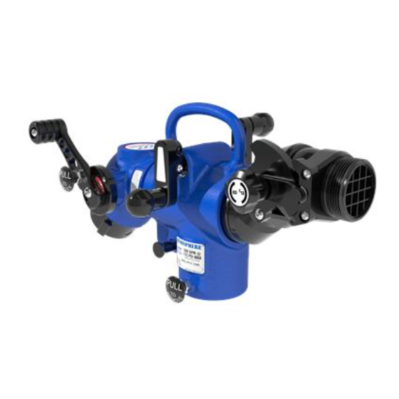
Hemisphere Monitor
(Shown with optional Max-Force nozzle)
Maximum Pressure at no flow:
300 PSI (20 bar)
Maximum Operating Condition:
175 PSI (12 bar) @ 500 GPM
(2000 l/min)
Hydrostatic Proof Test:
900 PSI (62 bar) per NFPA 1964
TASK FORCE TIPS LLC
MADE IN USA • tft.com
©Copyright Task Force Tips LLC 2013-2020
Transportable Monitor
HPM-B
Fixed Mount
HPM-D
Mount Block
HPM-A
I-Beam Clamp
HPM-C
Hitch Mount
HPM-E
Cross-Pin Mount
3701 Innovation Way, Valparaiso, IN 46383-9327 USA
HEMISPHERE
HPM-F
Tank Lip Clamp
800-348-2686 • 219-462-6161 • Fax 219-464-7155
™
HPM-G
Parallel Bar Clamp
HPM-H
Flex Clamp
LIX-740 July 21, 2020 Rev08
Advertisement
Table of Contents

Related Manuals for Task Force Tips HEMISPHERE


Summary of Contents for Task Force Tips HEMISPHERE
- Page 1 900 PSI (62 bar) per NFPA 1964 TASK FORCE TIPS LLC 3701 Innovation Way, Valparaiso, IN 46383-9327 USA 800-348-2686 • 219-462-6161 • Fax 219-464-7155 MADE IN USA • tft.com ©Copyright Task Force Tips LLC 2013-2020 LIX-740 July 21, 2020 Rev08...
- Page 2 TASK FORCE TIPS, INC. 3701 Innovation Way, Valparaiso, IN 46383-9327 USA 800-348-2686 • 219-462-6161 • Fax 219-464-7155 MADE IN USA • www.tft.com ©Copyright Task Force Tips, Inc. 2008-2016 LIA-355 May 26, 2016 Rev06 LIA-355 2.5” Hydrant Valve ©Copyright Task Force Tips LLC 2013-2020...
-
Page 3: Table Of Contents
4.9.1 CHAIN SAFETY 4.9.1.1 CHAIN BENDING 4.9.1.2 MINIMUM BEND RADIUS REQUIREMENT 4.9.1.3 CHAIN AND SHACKLE INSPECTION 4.9.1.4 ADDING CHAIN FOR LARGER OBJECTS 4.9.1.5 CHAIN POSITIONING 4.9.2 INSTALLING THE FLEX CLAMP ©Copyright Task Force Tips LLC 2013-2020 LIX-740 July 21, 2020 Rev08... -
Page 4: Meaning Of Safety Signal Words
Per NFPA 1962, if dissimilar metals are left coupled together, an anti-corrosive lubricant should be applied to the connection and the coupling should be disconnected and inspected at least quarterly. To prevent mechanical damage, do not drop or throw equipment. NOTICE ©Copyright Task Force Tips LLC 2013-2020 LIX-740 July 21, 2020 Rev08... -
Page 5: General Information
3.0 GENERAL INFORMATION The Hemisphere is a versatile, lightweight, and easy to deploy transportable monitor that gives the user the ability to quickly establish water flow in locations that ground monitors cannot. Since the Hemisphere doesn’t rely on gravity for stability, it can be pointed horizontal and down, in addition to up, unlike portable ground monitors. -
Page 6: Various Models And Terms
3.4 VARIOUS MODELS AND TERMS The Hemisphere can be installed on a variety of mounts, each of which includes a standard profile for attaching the Hemisphere monitor. The following sections identify the various parts and controls on a standard Hemisphere transportable monitor, and available mounts. -
Page 7: I-Beam Clamp/2" Hitch Mount (Hpm-A)
I-Beam Clamp/2” Hitch Mount 3.4.3 TANK LIP CLAMP (HPM-F) Cross-Pin Mount Fixed Jaw Tank Lip Cross-Pins Backbone Clamp Arm Crank Moveable Jaw Clamp Head Figure 3.4.3 Tank Lip Clamp ©Copyright Task Force Tips LLC 2013-2020 LIX-740 July 21, 2020 Rev08... -
Page 8: Parallel Bar Clamp (Hpm-G)
3.4.4 PARALLEL BAR CLAMP (HPM-G) Backbone Fixed Bar Clamp Cross-Pin Parallel Bars Cross-Pin Mount Cross-Pin Floating Bar Clamp Knob Eye Bolt Clamshell Figure 3.4.4 Parallel Bar Clamp ©Copyright Task Force Tips LLC 2013-2020 LIX-740 July 21, 2020 Rev08... -
Page 9: Flex Clamp (Hpm-H)
3.4.5 FLEX CLAMP (HPM-H) Cross-Pin Mount Backbone Chain Block Pull-Pin Slack Reducer Slot Chain Tensioner Magnetic Chain Catch Chain Bag Chain Crank Knob Extender Shackle Figure 3.4.5 Flex Clamp ©Copyright Task Force Tips LLC 2013-2020 LIX-740 July 21, 2020 Rev08... -
Page 10: Installing Clamps And Mounts
• Avoid situations posing a drop hazard to persons below The Hemisphere transportable monitor can be secured onto fixed mounts or to a backbone that can be attached to stationary objects using a series of different clamp types. The clamps are designed to restrain loads from only one monitor per backbone. -
Page 11: Maximum Flange Dimensions
Several orientations are possible when clamping to I-beams, stair rails, and other suitable geometry. Figure 4.1.1B shows some examples of possible orientations. Figure 4.1.1B Examples of I-Beam Clamp Installation ©Copyright Task Force Tips LLC 2013-2020 LIX-740 July 21, 2020 Rev08... -
Page 12: Installing The I-Beam Clamp
Don’t turn crank more than one turn after the jaws are fully seated and crank arm has stopped moving. Don’t tighten the crank with a wrench, tool, or cheater bar. ©Copyright Task Force Tips LLC 2013-2020 LIX-740 July 21, 2020 Rev08... -
Page 13: 2" Hitch Receiver Mount
Hitch Mount Assembly and Installation Using the hitch mount for anything other than mounting a monitor is a misuse of this product. NOTICE Never attempt to tow or pull with the hitch mount. ©Copyright Task Force Tips LLC 2013-2020 LIX-740 July 21, 2020 Rev08... -
Page 14: Fixed Mount (Hpm-B)
C) Bolt to the front of a surface by adding (2) 1/2” (13mm) HPM-E tapped holes and securing with 1/2” bolts. Cross-Pin Mount 1/2" Bolts Figure 4.5 Mounting Block Installation Options ©Copyright Task Force Tips LLC 2013-2020 LIX-740 July 21, 2020 Rev08... -
Page 15: Cross Pin Mount (Hpm-E)
3) Rotate the crank an additional half-turn until tight. Clamp head tight against tank lip Figure 4.7.2 Installing the Tank Lip Clamp ©Copyright Task Force Tips LLC 2013-2020 LIX-740 July 21, 2020 Rev08... -
Page 16: Parallel Bar Clamp (Hpm-G)
3, 5 All four clamshell clamps 3, 5 are latched tight Mount positioned with clearance for monitor Floating bar clamp Figure 4.8.1 Installing the Parallel Bar Clamp ©Copyright Task Force Tips LLC 2013-2020 LIX-740 July 21, 2020 Rev08... -
Page 17: Flex Clamp (Hpm-H)
If the corner radius is smaller than the gauge, the clamp should not be used without corner protection. Corner Radius Gauge Figure 4.9.1.2A Minimum Bend Radius Gauge SMALL Figure 4.9.1.2B Determining Acceptable Radius for Mounting Objects ©Copyright Task Force Tips LLC 2013-2020 LIX-740 July 21, 2020 Rev08... -
Page 18: Chain And Shackle Inspection
Install the upper and lower chains as far apart as possible on the mounting object. Always position the monitor between the chains to minimize the stress on the Flex Clamp. Figure 4.9.1.5 Positioning the Chain on the Mounting Object ©Copyright Task Force Tips LLC 2013-2020 LIX-740 July 21, 2020 Rev08... -
Page 19: Installing The Flex Clamp
5) Slide a chain link into the catch. A magnet will help hold the chain in the catch. Verify that the chain is tight and secure in the catch. Figure 4.9.2A Installing the Flex Clamp ©Copyright Task Force Tips LLC 2013-2020 LIX-740 July 21, 2020 Rev08... -
Page 20: Operating Instructions
5.1 INSTALLING THE MONITOR ONTO THE MOUNT The Hemisphere monitor is designed to be installed by one person by sliding the socket at the base of the monitor onto a mount. The monitor is not attached until the monitor release pin seats in the annular groove on the lower portion of the mount. Attachment should always be verified by attempting to pull the monitor off the mount. -
Page 21: Releasing The Monitor From The Mount
Rotation Axial Locked Lock Pin Rotation Released Pressurized Pin Position Indicator Return Spring Figure 5.3B Figure 5.3.C Rotation Lock in the Released Position Rotation Lock in the Locked Position ©Copyright Task Force Tips LLC 2013-2020 LIX-740 July 21, 2020 Rev08... -
Page 22: Rotational Lock Safely Mechanism
The figures below show the range of possible directions the Hemisphere nozzle can point overall, through combined rotations about all of its axes. The range shown, almost a complete hemisphere, is achievable without interrupting water flow. When that range is rotated about the monitor mount without water flowing, any point on a sphere, minus the 20 degree regions above and below the monitor, can theoretically be achieved as illustrated. -
Page 23: Pivoting The Outlet
180 degrees to make both cranks aligned, if preferred. Standard Standard Offset Aligned Extended Extended Offset Aligned Figure 5.5.3 Waterway Rotational Crank Arm Position Options ©Copyright Task Force Tips LLC 2013-2020 LIX-740 July 21, 2020 Rev08... -
Page 24: Quarter Turn Valve
6.2 AUTOMATIC, FIXED, AND SELECTABLE FLOW NOZZLES A variety of water or foam nozzles may be used with the Hemisphere. Automatic nozzles maintain a constant pressure by adjusting their opening to match the available flow. Consult the nozzle manufacturer for maximum flow and pressure ratings. In all cases do not exceed 500 gpm (2000 l/min) and/or 175 psi (12 bar) nozzle exit pressure. -
Page 25: Stream Straighteners
Task Force Tips LLC, 3701 Innovation Way, Valparaiso, Indiana 46383-9327 USA (“TFT”) warrants to the original purchaser of its Hemisphere Monitor (“equipment”), and to anyone to whom it is transferred, that the equipment shall be free from defects in material and workmanship during the five (5) year period from the date of purchase. -
Page 26: Maintenance
Any equipment taken out of service due to failure should be returned to the factory for repair or replacement. If you have any questions regarding the testing or maintenance of your valve, please call Task Force Tips at 800-348-2686. 9.0.1 DOUBLE BALL PIVOT SYNCHRONIZER AND LOCK MAINTENANCE It is important to clean, inspect, and maintain the synchronizing mechanism regularly, and before each use, as needed. -
Page 27: Lock Pin Assembly Maintenance
Any returns should include a note as to the nature of the problem and whom to reach in case of questions. Repair parts and service procedures are available for those wishing to perform their own repairs. Task Force Tips assumes no liability for damage to equipment or injury to personnel that is a result of user service. -
Page 28: Operation And Inspection Checklist
Operating equipment that has failed the checklist is a misuse of this equipment. TASK FORCE TIPS LLC 3701 Innovation Way, Valparaiso, IN 46383-9327 USA 800-348-2686 • 219-462-6161 • Fax 219-464-7155 MADE IN USA • tft.com ©Copyright Task Force Tips LLC 2013-2020 LIX-740 July 21, 2020 Rev08...
Need help?
Do you have a question about the HEMISPHERE and is the answer not in the manual?
Questions and answers