Table of Contents
Advertisement
Quick Links
G-Force
INSTRUCTION FOR INSTALLATION, OPERATION, AND MAINTENANCE
DANGER
3.5" Discharge
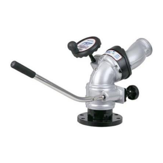
Tiller
2.5" Discharge
TASK FORCE TIPS LLC
MADE IN USA · tft.com
©Copyright Task Force Tips LLC 2004-2020
Understand manual before use. Operation of this device without understanding the manual and
receiving proper training is a misuse of this equipment. Obtain safety information at tft.com/
serial-number.
This equipment is intended for use by trained and qualified emergency services personnel for
firefighting. All personnel using this equipment shall have completed a course of education
approved by the Authority Having Jurisdiction (AHJ).
This instruction manual is intended to familiarize firefighters and maintenance personnel with the
operation, servicing, and safety procedures associated with this product. This manual should be
kept available to all operating and maintenance personnel.
Tiller
(see section 3.2)
for Flow/Pressure Operations Envelope
MONSOON™ MONITOR
SERIES
Dual Handwheel
3.5" Discharge
Dual Handwheel
2.5" Discharge
®
1
Remote Control (RC)
3.5" Discharge
Remote Control (RC)
2.5" Discharge
3701 Innovation Way, Valparaiso, IN 46383-9327 USA
800-348-2686 · 219-462-6161 · Fax 219-464-7155
LIY-200 November 5, 2020 Rev19
®
Advertisement
Table of Contents

Related Manuals for Task Force Tips MONSOON Series


Summary of Contents for Task Force Tips MONSOON Series
- Page 1 (see section 3.2) for Flow/Pressure Operations Envelope TASK FORCE TIPS LLC 3701 Innovation Way, Valparaiso, IN 46383-9327 USA 800-348-2686 · 219-462-6161 · Fax 219-464-7155 MADE IN USA · tft.com ©Copyright Task Force Tips LLC 2004-2020 LIY-200 November 5, 2020 Rev19...
- Page 2 6. Failure to follow these guidelines may result in death, burns or other severe injury. Fire and Emergency Manufacturers and Service Association FEMSA P.O. Box 147, Lynn eld, MA 01940 • www.FEMSA.org ©Copyright Task Force Tips LLC 2004-2020 LIY-200 November 5, 2020 Rev19...
- Page 3 800-348-2686 • 219-462-6161 • Fax 219-464-7155 800-348-2686 • 219-462-6161 • Fax 219-464-7155 MADE IN USA • www.tft.com MADE IN USA • tft.com ©Copyright Task Force Tips LLC 2008-2019 LIY-500 April 8, 2019 Rev14 ©Copyright Task Force Tips, Inc. 2013-2017 LIZ-050 July 25, 2017 Rev04 ©Copyright Task Force Tips LLC 2009-2018...
-
Page 4: Table Of Contents
6.6.2 STREAM STRAIGHTENERS WITH FOG NOZZLES 7.0 WARRANTY 8.0 MAINTENANCE 8.1 SERVICE TESTING 8.2 LUBRICATION 8.3 TROUBLESHOOTING 8.4 REPAIR 9.0 EXPLODED VIEWS AND PARTS LISTS 10.0 OPERATION AND INSPECTION CHECKLIST ©Copyright Task Force Tips LLC 2004-2020 LIY-200 November 5, 2020 Rev19... -
Page 5: Meaning Of Safety Signal Words
• Be aware that the monitor may be remotely operated • Keep hands and fingers away from pinch points on the monitor • Never operate the manual override while electric controls are in operation ©Copyright Task Force Tips LLC 2004-2020 LIY-200 November 5, 2020 Rev19... -
Page 6: General Information
Maximum Torque (Elevation) 80 ft·lbs 110 N·m Maximum Torque (Horizontal) 60 ft·lbs 80 N·m Speed (Elevation) 6 deg/sec Speed (Horizontal) 12 deg/sec Materials ANSI A356.0-T6 Aluminum, Stainless, Nylon Table 3.1 ©Copyright Task Force Tips LLC 2004-2020 LIY-200 November 5, 2020 Rev19... -
Page 7: Operating Envelope
Nozzle B flows 1000 gpm (3800 l/min), at 100 PSI (6.9 bar), K factor = 100 Nozzle C flows 1500 gpm (5700 l/min), at 100 PSI (6.9 bar), K factor = 150 Figure 3.2B 2.5” Monsoon Operating Envelope ©Copyright Task Force Tips LLC 2004-2020 LIY-200 November 5, 2020 Rev19... -
Page 8: Use With Salt Water
The Monsoon Monitor c omes in manual and electric remote controlled models. Manual models are available wi on both axis or a tiller bar model that uses a tiller bar to control horizontal rotation. Electric remote control models are available in a standard model (suitable for on top of pumpers), a Ladder model and a Platform model. The Ladder or Platform model has a smaller swing radius and has horizontal travel stops factory installed at 90° left and right (180° total).trol Figure 3.4A Manual Handwheel Monsoon Monitor ELEVATION HANDWHEEL TILLER HANDLE LOCKING KNOB Figure 3.4B Manual Tiller Bar Monsoon Monitor ©Copyright Task Force Tips LLC 2004-2020 LIY-200 November 5, 2020 Rev19... - Page 9 Monsoon RC Monitor MONITOR MOUNTED CONTROL STATION Anti-Back-Drive Gearbox Figure 3.4D Figure 3.4E Figure 3.4F Monsoon RC for Ladder or Platform Monsoon RC for Ladder Monsoon RC Standard Model ©Copyright Task Force Tips LLC 2004-2020 LIY-200 November 5, 2020 Rev19...
-
Page 10: Inlets And Outlets
3” NPT Y4420A 2.30 MALE CODE-RLF 4” NPT Y4430A 2.30 MALE CODE-RPF * SEE SECTION 3.6 OVERALL DIMENSIONS FOR NOMINAL MONITOR DIMENSIONS ** FOR QUICK CONNECT OPTIONS REFERENCE LIY-250 ©Copyright Task Force Tips LLC 2004-2020 LIY-200 November 5, 2020 Rev19... -
Page 11: Mating Products
3.5” NH MALE 3.5” BSP MALE Y4330ABN Y4310A 3.5” NPSH MALE Y4330AIN 4.0” BSP MALE Y4334ABP 2.5” NH MALE Y4311 2.5” BSP MALE X332BJ 2.5” NPSH MALE X332IJ Table 3.5.5 ©Copyright Task Force Tips LLC 2004-2020 LIY-200 November 5, 2020 Rev19... -
Page 12: Overall Dimensions
Manual Handwheel Monsoon (Shown without inlet fitting (see section 3.5) for additional height) Figure 3.6B Manual Tiller Bar Monsoon (Shown without inlet fitting (see section 3.5) for additional height) ©Copyright Task Force Tips LLC 2004-2020 LIY-200 November 5, 2020 Rev19... - Page 13 Figure 3.6C Monsoon RC Figure 3.6D Monsoon RC for Platform ©Copyright Task Force Tips LLC 2004-2020 LIY-200 November 5, 2020 Rev19...
-
Page 14: Installation
BOLTS 3” ANSI 125/150-DN80 PN20 0.75 152.5 4” ANSI 150-DN100 PN20 0.94 6” ANSI 150 Flange 10.9 25.4 241.3 DN80, PN16 Flange 0.87 DN100, PN16 Flange 0.87 Table 4.2 ©Copyright Task Force Tips LLC 2004-2020 LIY-200 November 5, 2020 Rev19... -
Page 15: Inlet Fitting Or Extend-A-Gun Installation
MONITOR BASE CLAMP Y4435 WASHER VW360x200-04 SOCKET HEAD SCREW 10-32 X 1-1/4 LONG Apply VSA-125 blue Loctite to threads on both VT10-32SH1.2 CYLINDER NUT Cylinder Nuts. Y4437 Figure 4.4A ©Copyright Task Force Tips LLC 2004-2020 LIY-200 November 5, 2020 Rev19... - Page 16 To avoid damage to the monitor, ensure Clamps ALTERNATE BOLTS do not interefere with RC monitor Power/Com WITH EACH HALF TURN cable and that Screws are not overtightened. Figure 4.4B ©Copyright Task Force Tips LLC 2004-2020 LIY-200 November 5, 2020 Rev19...
-
Page 17: Cable Routing For Extend-A-Gun
Extend-A-Gun Cable Routing The Extend-A-Gun manual override knob may be mounted in any of four possible orientations (90 degrees apart) relative to the Straight Ahead Reference Mark on the monitor. ©Copyright Task Force Tips LLC 2004-2020 LIY-200 November 5, 2020 Rev19... -
Page 18: Horizontal Rotation Travel Stops
INSTALLED ON THIS SIDE OF 8° LESS RIGHT TRAVEL WITH THE STOP BOLT EVERY ADJUSTMENT DISC INSTALLED ON THIS SIDE OF THE STOP BOLT STOP BOLT Figure 4.6B Horizontal Rotation Travel Stops ©Copyright Task Force Tips LLC 2004-2020 LIY-200 November 5, 2020 Rev19... -
Page 19: Elevation Travel Stops
(C) 30° BELOW Elevation travel with no Stop Bolts is HORIZTONAL 90° above and 45° below zero. SET SCREW #VT37-24SS250 STOP BOLT #Y4145 Figure 4.7B Elevation Travel Stop Locations ©Copyright Task Force Tips LLC 2004-2020 LIY-200 November 5, 2020 Rev19... -
Page 20: Nozzle Installation
A handwheel controls the monitor’s elevation direction. Clockwise rotation of the handwheel lowers the elevation and counterclockwise raises it. About 50 turns of the handwheel will give the complete 135 degree elevation travel range of the monitor. ©Copyright Task Force Tips LLC 2004-2020 LIY-200 November 5, 2020 Rev19... -
Page 21: Tiller Bar Control
11/16" (18 mm) Cut here to shorten shaft Figure 5.5 Wrenching Hex and Cutting Locations ©Copyright Task Force Tips LLC 2004-2020 LIY-200 November 5, 2020 Rev19... -
Page 22: Flow Characteristics
2 1/4" TIP (PRESSURE IS NOZZLE EXIT PITOT PRESSURE) 2" TIP 2 3/4" TIP 2 1/2" TIP 1000 1200 1400 1600 1800 2000 FLOW (GPM) Figure 6.1B YST-4NN Flow Graph ©Copyright Task Force Tips LLC 2004-2020 LIY-200 November 5, 2020 Rev19... - Page 23 2.75 INCH TIP 20.0 40.0 60.0 80.0 60 PSI 80 PSI 100 PSI 50 PSI 40.0 80.0 120.0 160.0 200.0 240.0 280.0 HORIZONTAL DISTANCE (FEET) Figure 6.1C YST-4NN Reach Graphs ©Copyright Task Force Tips LLC 2004-2020 LIY-200 November 5, 2020 Rev19...
-
Page 24: Mst-4Nj Stacked Tips Flow And Reach
STACK TIP PERFORMANCE (PRESSURE IS NOZZLE EXIT PITOT PRESSURE) 1 1/2" TIP 2" TIP 1 3/8" TIP 1 3/4" TIP 1000 1200 1400 1600 FLOW (GPM) Figure 6.2B MST-4NJ Flow Graph ©Copyright Task Force Tips LLC 2004-2020 LIY-200 November 5, 2020 Rev19... - Page 25 2 INCH TIP HORIZONTAL DISTANCE (M) 80.0 60 PSI 80 PSI 100 PSI 40 PSI 40.0 80.0 120.0 160.0 200.0 240.0 280.0 HORIZONTAL DISTANCE (FEET) Figure 6.2C MST-4NJ Reach Graphs ©Copyright Task Force Tips LLC 2004-2020 LIY-200 November 5, 2020 Rev19...
-
Page 26: Effects Of Elevation And Wind On Stream Reach
2.00 INCH TIP , 100 PSI, 1190 GPM HORIZONTAL DISTANCE (M) TAILWIND 20 MPH (32 km/h) HEADWIND 20 MPH (32 km/h) NO WIND HORIZONTAL DISTANCE (FEET) Figure 6.2B Effects of Wind on Reach ©Copyright Task Force Tips LLC 2004-2020 LIY-200 November 5, 2020 Rev19... -
Page 27: Automatic Masterstream Nozzles
2000 2250 2500 FLOW (GPM) Figure 6.5A 3.5” Monsoon Monitor Friction Loss FLOW (LPM) 1000 2000 3000 4000 1000 1250 FLOW (GPM) Figure 6.5B 2.5” Monsoon Monitor Friction Loss ©Copyright Task Force Tips LLC 2004-2020 LIY-200 November 5, 2020 Rev19... -
Page 28: Stream Straighteners
Use of a stream straightener with a fog nozzle is not recommended. NOT OK Figure 6.6.2 ©Copyright Task Force Tips LLC 2004-2020 LIY-200 November 5, 2020 Rev19... -
Page 29: Warranty
WARRANTY Task Force Tips LLC, 3701 Innovation Way, Valparaiso, Indiana 46383-9327 USA (“TFT”) warrants to the original purchaser of its products (“equipment”), and to anyone to whom it is transferred, that the equipment shall be free from defects in material and workmanship during the five (5) year period from the date of purchase. -
Page 30: Maintenance
Any equipment taken out of service due to failure should be returned to the factory for repair or replacement. If you have any questions regarding the testing or maintenance of your valve, please call Task Force Tips at 800-348-2686. SERVICE TESTING In accordance with NFPA 1962, equipment must be tested a minimum of annually. -
Page 31: Repair
Repair parts and service procedures are available for those wishing to perform their own repairs. Task Force Tips assumes no liability for damage to equipment or injury to personnel that is a result of user service. Contact the factory or visit the web site at tft.com for parts lists, exploded views, test procedures and troubleshooting guides. -
Page 32: 10.0 Operation And Inspection Checklist
Operating equipment that has failed the checklist is a misuse of this equipment. TASK FORCE TIPS LLC 3701 Innovation Way, Valparaiso, IN 46383-9327 USA 800-348-2686 · 219-462-6161 · Fax 219-464-7155 MADE IN USA · tft.com ©Copyright Task Force Tips LLC 2004-2020 LIY-200 November 5, 2020 Rev19...
Need help?
Do you have a question about the MONSOON Series and is the answer not in the manual?
Questions and answers