
Related Manuals for Transition Networks MIL-SEM24T4GPA


Summary of Contents for Transition Networks MIL-SEM24T4GPA
- Page 1 20 10/100/1000T + 4 10/100/1000T RJ-45/SFP Combo Ports SNMP Lite Managed Switch MIL-SEM24T4GPA User Manual Rev. A2 2007-12-28...
- Page 2 Transition Networks will in no case cover damages arising out of the product being used in a negligent fashion or manner. Trademarks The MiLAN logo and Transition Networks trademarks are registered trademarks of Transition Networks in the United States and/or other countries. To Contact Transition Networks...
-
Page 3: Fcc Warning
FCC Warning This Equipment has been tested and found to comply with the limits for a Class A digital device, pursuant to Part 15 of the FCC rules. These limits are designed to provide reasonable protection against harmful interference in a residential installation. -
Page 4: Table Of Contents
Contents Introduction ........................6 Features ........................6 Software Feature......................7 Package Contents....................8 Hardware Description ....................10 Physical Dimension....................10 Front Panel ......................10 LED Indicators......................11 Rear Panel ......................12 Desktop Installation....................12 Power On .......................13 Network Application....................14 Desktop Application ....................14 Segment Application ....................14 Console Management ....................15 Connecting to the Console Port ................15 Login in the Console Interface ................15 CLI Management....................17 Web-Based Management....................18... - Page 5 Spanning Tree......................33 RSTP System Configuration ................33 RSTP Port Configuration.................34 Spanning Tree Status ....................35 RSTP - Port Configuration ................35 SNMP Setting......................37 QoS Configuration....................38 QoS DSCP Mapping ..................39 Priority Queue Service ..................40 QoS Vlan Tag Priority Mapping...............42 Filter ........................42 IGMP Configuration....................44 IGMP Status......................45 Rate Limit Configuration..................45 802.1X Configuration .....................47 802.1X Parameters ..................49...
-
Page 6: Introduction
Introduction The MIL-SEM24T4GPA Switch is a multi-port switch that can be used to build high-performance switched workgroup networks. It provides wire-speed, Fast Ethernet switching function that allows high-performance, low-cost connection. The Switch features a store-and-forward switching and it can auto-learn and store source address on an 8K-entry MAC address table. -
Page 7: Software Feature
IP Security: IP address security management to prevent unauthorized intruder Login Security: IEEE802.1x/RADIUS IGMP Snooping v1,v2 Spanning Tree Support IEEE 802.1d Spanning Tree Support IEEE 802.1w Rapid Spanning Tree Bandwidth Control Ingress Packet Filter and Egress Rate Limit Broadcast/Multicast Packet Filter Control SNMP Trap Device cold start Port Link up/Link down... -
Page 8: Package Contents
Service Support IEEE 802.1p class of service, per port Class of Service provides 4 priority queues Port Mirror Support mirroring type: RX packet Support IGMP snooping v1, v2 IGMP The IGMP supports 255 multicast groups Support 1 IP address that has permission to access the switch management and to prevent IP Security unauthorized intruder... - Page 9 Unpack the contents of the MIL-SEM24T4GPA Switch and verify them against the checklist below. (1) MIL-SEM24T4GPA Switch (4) Rubber Feet (1) Power Cord (1) RS-232 cable (1) User Manual 20 10/100/1000T + 4 10/100/1000T/Mini-GBIC Four Rubber Pads Power Cord Combo SNMP Lite Managed Switch...
-
Page 10: Hardware Description
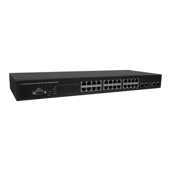
161mm(D) x 44mm(H) Front Panel The Front Panel of the MIL-SEM24T4GPA Switch consist of 24 x auto-sensing 10/100/1000Mbps Ethernet RJ-45 ports (automatic MDI/MDIX), 4 SFP ports, and the LED indicators are also located on the front panel of the switch. -
Page 11: Led Indicators
LED Indicators LED Indicators The following table provides descriptions of the LED statuses and meaning. They provide a real-time indication of systematic operation status. Status Description Green Power On Power No power input The port is operating at the speed of 1000 Green 1000Mbps. -
Page 12: Rear Panel
Blinks Collision packet detection No device attached. Rear Panel The 3-pronged power plug is located at the Rear Panel of the MIL-SEM24T4GPA Switch as shown in figure. The Switches will work with AC in the range 100-240V AC, 50-60Hz. MIL-SEM24T4GPA... -
Page 13: Power On
Make sure mounting surface on the bottom of the Switch is grease and dust free. Remove adhesive backing from your Rubber Feet. Apply the Rubber Feet to each corner on the bottom of the Switch. These footpads can prevent the Switch from shock/vibration. Power On Connect the power cord to the power socket on the rear panel of the Switch. -
Page 14: Network Application
Network Application This section provides you a few samples of network topology in which the switch is used. In general, the MIL-SEM24T4GPA Switch is designed to be used as a desktop or segment switch. Desktop Application The MIL-SEM24T4GPA Switch is designed to be a desktop size switch that is an ideal solution for small workgroup. -
Page 15: Console Management
Console Management Connecting to the Console Port Use the supplied RS-232 cable to connect a terminal or PC to the console port. The connected terminal or PC must support the terminal emulation program. Connecting the switch to a terminal via RS-232 cable Login in the Console Interface When the connection between Switch and PC is ready, turn on the PC and run a terminal emulation program or Hyper Terminal and configure its communication... - Page 16 The settings of communication parameters After finishing the parameter settings, click “OK“. When the blank screen shows up, type in “root” then press enter button to get into command line mode. Please see below figure for login screen. CLI command interface...
-
Page 17: Cli Management
CLI Management The system supports console management (CLI command). After you login to the system, you will see a command prompt. CLI command interface... -
Page 18: Web-Based Management
Web-Based Management This section introduces the configuration and functions of the Web-Based management. About Web-based Management On CPU board of the switch, there is an embedded HTML web site residing in flash memory, which offers advanced management features and allow users to manage the switch from anywhere on the network through a standard browser such as Microsoft Internet Explorer. -
Page 19: System Login
System Login The default values are as below: IP Address: 192.168.1.77 Subnet Mask: 255.255.255.0 Default Gateway: 192.168.1.254 Password: root Login Interface System Configuration System parameters information list as below, and the other parameters of system can be configured as well. MAC Address: the unique hardware address assigned by manufacturer (default) - Page 20 S/W Version: the Software Version of Kernel H/W Version: the Hardware Version of Switch Active IP Address: the current IP Address Active Subnet Mask: the current IP Subnet Mask Active Gateway: the current Gateway DHCP Server: the DHCP Server IP Address Lease Time Left: the DHCP lease time.
-
Page 21: Console Info
DHCP Enable: Enable DHCP Client Function Fallback IP Address: Assign the switch IP address (The default IP is 192.168.1.77) Fallback Subnet Mask: Assign the switch IP Subnet Mask Fallback Gateway: Assign the switch Gateway (The default value is 192.168.1.254) TFTP Server Enabled: Mark this check box to enable the TFTP server. Management VLAN: Assign a number of VLAN group between 1 and 4094. -
Page 22: Port Status
Port Status This page displays the port status of linking, auto-negotiation, flow control and max frame. Link: Displays the current connection speed. Auto-Negotiation: Displays the negotiation status of the port. Flows Control: Displays the status of flow control. MaxFrame (1518 ~ 9600): Displays the Maximum Frame Size. Drop frames after excessive collisions: When this check box is marked, the switch will drop the frames after excessive collisions. -
Page 23: Statistics Overview For All Ports
Port Status interface Statistics Overview for all ports The following information provides the current port statistics Press Clear button to clean all counts. -
Page 24: Port Configuration
And then, click Refresh to get the new setting information as below: Statistics Overview interface Port Configuration You can configure the linking mode, flow control and maximum frame size of the ports by this page. Link: Displays the current connection speed. Mode: Displays the negotiation status of the port. -
Page 25: Aggregation/Trunking Configuration
the switch will drop the frames after excessive collisions. Click Refresh to get the newest status. Port Configuration interface Aggregation/Trunking Configuration Port trunk allows multiple links to be bundled together and act as a single physical link for increased throughput. It provides load balancing, and redundancy of links in a... -
Page 26: Port Mirroring
switched inter-network. Actually, the link does not have an inherent total bandwidth equal to the sum of its component physical links. Traffic in a trunk is distributed across an individual link within the trunk in a deterministic method that called a hash algorithm. -
Page 27: Vlan Setting
to be monitored. And then, click Apply to apply the configuration Or, Click Refesh to reset the configuration before applying Port Mirroring interface VLAN Setting A Virtual LAN (VLAN) is a logical network grouping that limits the broadcast domain, which would allow user to isolate network traffic, and therefore only the members of VLAN will receive traffic from the members of the same VLAN. -
Page 28: Vlan Port Setting
devices are still plugged into the same switch physically. Assign the VLAN ID in number between 1 and 4094. And then, click add all to mark the 24 check boxes at the same time. clear all And then, click to clear the 24 check boxes at the same time. Grouping the members of VLAN. - Page 29 Tagged: Outgoing frames with VLAN-Tagged After that, click Apply to apply the configuration. Or, click Refresh to reset the configuration before applying VLAN Port Setting interface...
-
Page 30: Lacp Setting
LACP Setting The Link Aggregation Control Protocol (LACP) provides a standardized means for exchanging information between Partner Systems on a link to allow their Link Aggregation Control instances to reach agreement on the identity of the Link Aggregation Group to which the link belongs, move the link to that Link Aggregation Group, and enable its transmission and reception functions in an orderly manner. -
Page 31: Lacp Status
LACP Setting interface LACP Status When the LACP aggregator has been setup, the LACP status information will display as below: Protocol Active: Displays whether the LACP protocol is active. Partner Port Number: Displays the partner port number which is connecting to this port. - Page 32 LACP Status interface...
-
Page 33: Spanning Tree
Spanning Tree The Rapid Spanning Tree Protocol (RSTP) is an evolution of the Spanning Tree Protocol and provides for faster spanning tree convergence after a topology change. The system also supports STP and the system will automatically detect the connected device that is running STP or RSTP protocol. RSTP System Configuration System Priority: A value used to identify the root bridge. -
Page 34: Rstp Port Configuration
RSTP Configuration interface RSTP Port Configuration Protocol Enable: to enable or disable the port protocol Edge: The port directly connected to end stations cannot create bridging loop in the network. To configure the port as an edge port, mark the port... -
Page 35: Spanning Tree Status
Path Cost: The cost of the path to the other bridge from this transmitting bridge at the specified port. Enter a number 1 through 200000000 And then, click Apply to apply the configuration Or, click Refresh to reset the configuration before applying Spanning Tree Status Click Refresh... - Page 36 P2P: Some of the rapid state transactions that are possible within RSTP are dependent upon whether the port concerned can only be connected to one other bridge exactly (i.e. it is served by a point-to-point LAN segment), or can be connected to two or more bridges (i.e. it is served by a shared medium LAN segment).
-
Page 37: Snmp Setting
RSTP Port Status interface SNMP Setting Simple Network Management Protocol (SNMP) is the protocol developed to manage nodes (servers, workstations, routers, switches and hubs etc.) on an IP network. SNMP enables network administrators to manage network performance, find and solve network problems, and plan for network growth. Network management systems learn of problems by receiving traps or change notices from network devices implementing SNMP. -
Page 38: Qos Configuration
SNMP Setting interface SNMP enabled: Mark the check box to enable SNMP. SNMP Contact: Displays System contact. SNMP Location: Displays System location. SNMP Trap destination: Assign the IP address of the destination for receiving the SNMP trap. SNMP Read Community: Read only community string. Enables requests accompanied by this string to display MIB-object information. -
Page 39: Qos Dscp Mapping
Port Priority: Select the priority level – low, normal, medium, or high. And then, click Apply to apply the configuration. Or, click Refresh to reset the configuration before applying. QoS Configuration interface QoS DSCP Mapping Change to Qos DSCP Mapping tab: DSCP [0- 63]: The system provides 0~63 TOS priority level. -
Page 40: Priority Queue Service
IP packet is received, the system will check the TOS level value in the IP packet that has received. For example, user set the TOS level 25 is high. The port 1 is following the TOS priority policy. When the packet received by port 1, the system will check the TOS value of the received IP packet. - Page 41 the high priority queue services are finished. Or otherwise, you can check the Weighted Round Robin/WRR radio button for the queue service to be served in compliance with WRR. Priority Queue Service interface And then, click Apply to apply the configuration Or, Click Refesh to reset the configuration before applying...
-
Page 42: Qos Vlan Tag Priority Mapping
QoS Vlan Tag Priority Mapping You can pull down the selection item from Vlan Tag 0 to Vlan Tag 7 of each port to assign the priority. There are 4 priority selections—low, normal, medium and high. QoS VLAN Tag Priority Mapping interface Filter Source IP Filter Mode: Select the source IP mode –... - Page 43 IP Address: When Mode is set in Static mode, user has to assign an IP address manually. IP Mask: When Mode is set in Static mode, user has to assign the IP mask manually. DHCP Server Allowed: Mark this check box for DHCP Server allowed. And then, click Apply to apply the configuration...
-
Page 44: Igmp Configuration
Filter Configuration interface IGMP Configuration IGMP Enabled: Mark the check box for enabling IGMP function. Router Ports: Mark the check box to the port number for checking. Unregistered IPMC Flooding enabled: The default state is checked to enable the unregistered IP MultiCast flooding. IGMP Snooping Enabled: Mark the check box for enabling IGMP Snooping function. -
Page 45: Igmp Status
IGMP Status Querier: Displays the status of the querier. Queries transmitted: Displays the amount of the transmitted queries. Queries received: Displays the amount of the received queries. v1~v3 Reports: Displays the IGMP reports of version 1~3. Click Refesh to reset the status. IGMP Status interface Rate Limit Configuration Storm Control (Number of frames per second) - Page 46 Policer: Assign the policer rates in the range of 128K~3968K bps or No limit. Shaper: Assign the shaper rates in the range of 128K~3968K bps or No limit. And then, click Apply to apply the configuration Or, Click Refesh to reset the configuration before applying Rate Limit interface...
-
Page 47: 802.1X Configuration
802.1X Configuration 802.1x is an IEEE authentication specification that allows a client to connect to a wireless access point or wired switch but prevents the client from gaining access to the Internet until it provides credentials, like a user name and password that are verified by a separate server. - Page 48 802.1X Configuration interface...
-
Page 49: 802.1X Parameters
802.1X Parameters Click the tab of 802.1X Parameters or press the Parameters button to change to the 802.1X Parameters page. Reauthentication Enable: To enable the re-authentication mode. Reauthentication period (1~3600 seconds): Set the period of time after which clients connected must be re-authenticated. EPA Timeout (1~255 seconds): Set the period of time the switch waits for a supplicant response to an EAP request And then, click... -
Page 50: Mac Address Table Control
802.1X Statistics interface MAC Address Table Control MAC Address Entry No: The index of the MAC address table. MAC Address: The MAC address of the entry. Port: Displays the port number from which the MAC address was learned. VLAN ID: Displays the VLAN ID of the port. Type: Displays the information of the MAC address that was learned automatically by the switch or built by user. -
Page 51: Static Mac Address Entries In Permanent Table
Dump MAC Address Table interface Static MAC Address Entries in Permanent Table This page displays the static MAC address information. Click Refesh to get the newest information. -
Page 52: Configuration Upload
Static MAC Address Entries in Permanent Table interface Configuration Upload User can backup the current configuration as a file by clicking Download button. Or you can restore the configuration from an existing file by clicking Upload button. Configuration Upload & Download interface Factory Default Reset the switch to default... -
Page 53: Software Upload
Factory Default interface Software Upload The system provides the Web GUI firmware update function which allow user to update the switch firmware. Click to locate the firmware. And then, press Upload to update the firmware. Firmware Upload interface Reboot Reboot the switch in software reset. All the configurations will be reminded. Click Yes to restart the system... -
Page 54: Configuration File Transfer
Warm Restart interface Configuration File Transfer The system provides the Web GUI configuration file transfer function which would allow user to backup and restore the switch configuration. Click Browse to locate the file. And then, press Upload to upload the file. For restoring the file, press Download to restore the file. - Page 55 Logout interface...
-
Page 56: Troubleshooting
Troubleshooting This section is intended to help user solve the most common problems on the MIL-SEM24T4GPA Switch. Incorrect connections The switch port can automatically detect straight or crossover cable when user link switch with other Ethernet device. As for the RJ-45 connector, it should use correct UTP or STP cable;... -
Page 57: Improper Network Topologies
feet). Gigabit port should use Cat-5 or cat-5e cable for 1000Mbps connections. The length does not exceed 100 meters. Improper Network Topologies It is important to make sure that you have a valid network topology. Common topology faults include excessive cable length and too many repeaters (hubs) between end nodes. -
Page 58: Technical Specifications
Technical Specifications This section provides the specifications of the MIL-SEM24T4GPA Switch and the following table lists these specifications. IEEE802.3 10BASE-T IEEE802.3u 100BASE-TX IEEE802.3z Gigabit fiber IEEE802.3ab 1000Base-T IEEE802.3x Flow control and Back pressure Standards IEEE802.3ad Port trunk with LACP IEEE802.1d Spanning tree protocol IEEE802.1w Rapid spanning tree... - Page 59 Jumbo Packet 10Kbytes Dimensions 440mm(W) x 161mm(D) x 44mm(H) MAC Address 8K MAC address table with Auto learning function -40 ~70 , 95% RH Storage Temp. Operating Humidity 10% ~ 95% (Non-condensing) 0 ~45 Operational Temp. Power Supply AC 100~240V, 50/60Hz Power Consumption 17.9 Watts (Maximum) Ventilation...
Need help?
Do you have a question about the MIL-SEM24T4GPA and is the answer not in the manual?
Questions and answers