Table of Contents

Related Manuals for TECHFASS APS mini Plus MREM 65 Series


Summary of Contents for TECHFASS APS mini Plus MREM 65 Series
- Page 1 MREM 65 APS mini Plus reader modules User’s guide © 2004 – 2019, TECH FASS s.r.o., Věštínská 1611/19, 153 00 Prague, Czech Republic, www.techfass.cz, techfass@techfass.cz (Date of release: 2019/06/03, valid for FW version 5.12)
-
Page 2: Table Of Contents
1 Content 1 Content ........................2 2 Product description ..................... 3 MREM 65 BK reader module ................3 MREM 65 GR reader module ................3 3 Technical parameters ....................4 Product version ....................4 Technical features....................4 Special accessories ..................... 5 Using WIO 22 module for remote output control .......... -
Page 3: Product Description
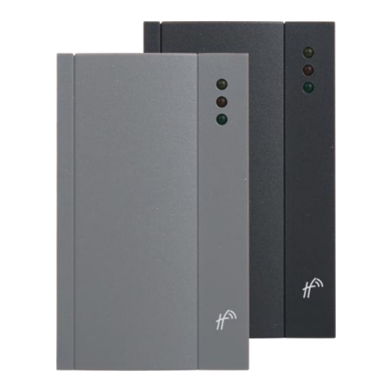
2 Product description MREM 65 reader modules (125 kHz readers with an embedded single door controller) are designed for connection to the RS 485 bus of APS mini Plus access control system, or for standalone operation. It is possible to connect up to 32 reader modules to a single line of the APS mini Plus system. -
Page 4: Technical Parameters
✓ ✓ MREM 65 GR – EM Dark grey 53465201 Table 1: Product version – TECHFASS factory 125 kHz ID media reading; – 125 kHz ID media reading; 3.2 Technical features 8 ÷ 15 VDC (SELV) Supply voltage Typical 80 mA... -
Page 5: Special Accessories
3.3 Special accessories 51900200 Magnet for Hall probe WIO 22 51901200 Remote control module, 2x relay Table 3: Special accessories 3.4 Using WIO 22 module for remote output control WIO 22 remote control WIEGAND relay module is designated for secure output control of APS system reader modules. -
Page 6: Standard Connection
4.2 Standard connection Input 1 Door contact, active when door closed; REX button Request to exit button or handle contact, active when button or Input 2 handle pressed; Tamper; Disabling function Output 1 (transistor) Door lock control (configurable polarity, default 0V for lock release) Alarm output Low power transistor output (+5 V in any alarm state) External tamper (Standard operating mode) -
Page 7: Mounting And Removal The Module
Nearby metal surfaces may cause a decrease in reading distance and speed. This is caused by the combined effects of parasitic capacitance and conductance. 4.5 Mounting and removal the module First fasten the base directly to the wall using two relevant fasteners, see Pic. 3. Then set the housing on the upper part of the base and rotate the housing until the both parts snaps down. -
Page 8: Setting Parameters Of The Reader Module
Enabled / Disabled Enabled Strike closed Enabled / Disabled Enabled Table 8: Configurable parameters 5.2 Reader module parameters setting Detailed instructions for setting reader module parameters are described in the APS Reader configuration program user’s guide available address http://www.techfass.cz/files/m_aps_miniplus_reader_en.pdf. Page 8... -
Page 9: Reader Module Functioning
6 Reader module functioning The reader module supports the following functions: • Standard “Door Open” function. • Door status monitoring. • Exit-devices contact monitoring. • Alarm output activated / acoustic signalization activated when any alarm condition occurs. The “Door Open” function can be activated in 3 different ways: •... -
Page 10: Alarm States
6.3 Alarm states The reader module can get in following alarm states: 1) Tamper alarm 2) Forced door alarm 3) Door ajar alarm 4) Antipassback alarm (Time APB alarm, Zone APB alarm) 5) ID with Alarm flag alarm Alarm state reporting is performed as follows: •... -
Page 11: Standard Operating Modes
– in combined systems with WIEGAND output readers with a fixed user’s guide available at WIEGAND data format IDs (more information in APS Reader http://www.techfass.cz/files/m_aps_miniplus_reader_en.pdf). 6.6 Wiegand interface configuration 6.6.1 Standard operating mode This is the module default operating mode. The Wiegand interface is used for controlling the WIO 22 module in this configuration. -
Page 12: Programming Mode
(tamper signal = transistor switched on) Table 10: Signal function in WIEGAND operating mode Since the FW version 5.09 the reading synchronization of a couple of TECHFASS readers implemented, enabling to cancel the mutual disturbance of the modules. The reader module offers the... - Page 13 address setting mode (for modules with HW address setting via the communication line). The module’s functionality in programming mode can be seen in pictures 5 a-d. It is not possible to use time schedules when inserting cards in programming mode, therefore cards are always valid.
- Page 14 6.7.3 Deleting cards „above or below“ If a user loses his ID medium, it is usually impossible to delete the ID from the memory with the procedure described in the previous chapter, since the medium is no longer available (with an exception of entering the code at the keypad). Following procedure can be used for deleting such ID.
- Page 15 6.7.4 Deleting all cards from the reader’s memory Follow these steps for deleting all cards from the reader module’s memory: Step 1 Step 2 Step 3 Read the programming card Read the programming card The reader module goes for deleting: the reader goes for deleting 5 times in a row;...
-
Page 16: Id Expiration Function
• – Delete it Card 4 gets lost using the card 2, which is available, and using the procedure from chapter 6.7.3 – Read + (inserting) programming card, then 5x + (inserting) programming card again, then card 2, and finally + (inserting) programming card again. -
Page 17: Antipassback Function
6.10 Antipassback function This function is implemented since the FW version 5.0. The Antipassback function is defined in two ways: • – user cannot repeatedly use his ID for defined time Time APB • – user cannot repeatedly enter an area, where he is already present Zone APB The Antipassback function is used only for the... -
Page 18: Disabling Function
The disabling status changes and disabled actions are logged in the events archive. 6.12 Reading synchronization Since the FW version 5.09 the reading synchronization of a couple of TECHFASS readers implemented, enabling to cancel the mutual disturbance of the modules. The reader module offers to use the IO synchronization... -
Page 19: Simplified Access Rights Evaluation
7 Simplified access rights evaluation The model of access rights contains time schedules and a table of holidays. A block diagram for access right evaluation can be seen in Pic.6. READING ID ID FOUND ACCESS DRIVEN BY TIME SCHED. HOLIDAY? ACCESS ALWAYS GRANTED ACCESS GRANTED... -
Page 20: Placing A Magnet For Tearing-Off Indication
Mount the reader module in formerly prepared holes mounted with plugs. Pic. 7: Magnet placement 9 Useful links • Wiring diagrams: http://techfass.cz/diagrams-aps-mini-plus-en.html • Program equipment: http://techfass.cz/software-and-documentation-en.html Page 20...
Need help?
Do you have a question about the APS mini Plus MREM 65 Series and is the answer not in the manual?
Questions and answers