Table of Contents
Advertisement
Advertisement
Table of Contents

Related Manuals for Hantek HDG2000B Series


Summary of Contents for Hantek HDG2000B Series
- Page 1 HDG2000B series Functions and Arbitrary Waveform Generator User manual (V1.2)
-
Page 2: Table Of Contents
Content Copyright Declaration ....................1 Safety Requirements ....................2 General Safety Summary ................... 2 Safety Terms and Symbols ..................3 Product Scrapping ..................... 3 Brief Introduction ...................... 4 Chapter 1 Quick Start ..................... 6 1.1 General Inspection ....................7 1.2 Front Panel ......................7 1.3 Rear Panel ...................... - Page 3 4.5 Set the Harmonic Amplitude ................30 4.6 Set the Harmonic Phase ..................30 Chapter 5 Modulated Waveform ................31 5.1 AM Modulation ....................32 5.1.1 Select AM Modulation ................32 5.1.2 Carrier Waveform Shape ................. 32 5.1.3 Carrier Frequency ..................32 5.1.4 Modulating Waveform Source ..............
- Page 4 5.6.6 Hopping Frequency.................. 44 5.7 2PSK ........................45 5.7.1 Select 2PSK Modulation ................45 5.7.2 Carrier Waveform Shape ................. 45 5.7.3 Carrier Phase ................... 45 5.7.4 Modulating Waveform Source ..............46 5.7.5 2PSK Rate ....................46 5.7.6 Modulating Phase ..................46 5.8 BPSK .........................
- Page 5 5.13.1 Select PWM Modulation ................. 54 5.13.2 Carrier Waveform Shape ............... 54 5.13.3 Duty Cycle ..................... 54 5.13.4 Modulating Waveform Source ..............54 5.13.5 Modulating Waveform Frequency ............55 5.13.6 PWM Deviation ..................55 Chapter 6 Sweep ..................... 57 6.1 Select Frequency Sweep ................... 58 6.2 Start Frequency and Stop Frequency ..............
- Page 6 10.4.4 Intensity ....................79 10.4.5 System Information ................79 10.4.6 Clock Source ..................79 10.5 Print ......................... 80 10.6 Update ......................80 Chapter 11 Remote Control ..................81 11.1 Install Keysight IO libraries suite ..............82 11.2 Remote Control via USB .................. 86 Appendix A Specifications ..................
-
Page 7: Copyright Declaration
Hantek reserves all rights to modify this document without prior notice. Please contact Hantek for the latest version of this document before placing an order. Hantek has made every effort to ensure the accuracy of this document but does not guarantee the absence of errors. Moreover, Hantek assumes no responsibility in obtaining permission and authorization of any third party patent, copyright or product involved in relation to the use of this document. -
Page 8: Safety Requirements
Safety Requirements General Safety Summary Read the following safety precautions to avoid injury and prevent damage to this product or any products connected to it. To evade potential hazards, use this product only as specified. Only qualified personnel should perform maintenance. Avoid fire or personal injury. -
Page 9: Safety Terms And Symbols
Safety Terms and Symbols Terms on the product. The following terms may appear on the product: Danger It represents that harms may be caused to you at once if you perform the operation. Warning It represents that latent harms may be caused to you if you perform the operation. -
Page 10: Brief Introduction
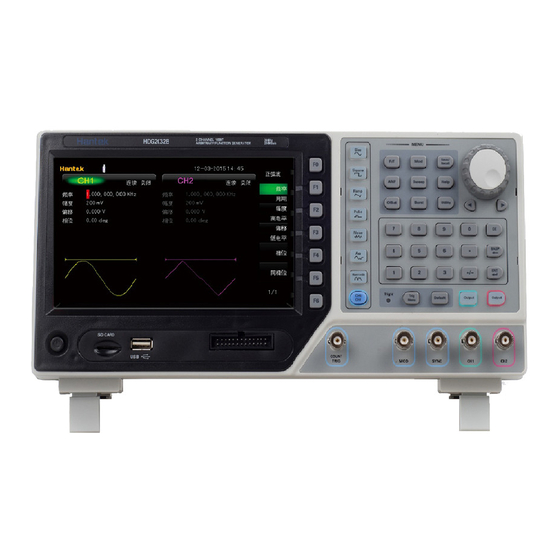
Brief Introduction HDG2000B Series is a series of synthesized waveform generators with built-in arbitrary waveform and pulse capabilities. Features: 7 inch, 16K true color TFT display, WVGA(800X480) 100 MHz, 80 MHz, 60 MHz, and 30 MHz maximum sine output frequency ... - Page 11 Models Model Channels Bandwidth Sample Rate HDG2102B 100MHz 500MS/s HDG2082B 80MHz 500MS/s HDG2062B 60MHz 500MS/s HDG2032B 30MHz 500MS/s User Manual...
-
Page 12: Chapter 1 Quick Start
Chapter 1 Quick Start This chapter introduces the front panel, rear panel, user interface and parameter setting method as well as precautions when using the instrument for the first time. General Inspection Front Panel Rear Panel Prepare Instrument for Use ... -
Page 13: General Inspection
1.1 General Inspection Please check the instrument as following steps after receiving an oscilloscope: Check the shipping container for damage: Keep the damaged shipping container or cushioning material until the contents of the shipment have been checked for completeness and the instrument has been checked mechanically and electrically. - Page 14 HDG2000B can use internal or external clock (refer to the introduction in "Clock Source"). When internal clock source is used, the connector (used as 10MHz Out) can output 10MHz clock signal generated by the internal crystal oscillator of the generator. ...
- Page 15 an operator "-" before the numbers. (For the use method of the numeric keyboard, refer to the introduction in "Parameter Setting Method"). 15. Direction Keys When using the knob and direction keys to set parameters, the direction keys are used to switch the digits of the parameter.
-
Page 16: Rear Panel
22. Menu softkey Correspond to the left menus respectively. Press any softkey to activate the corresponding menu. 23. LCD 800 × 480 TFT color LCD is used to display the current function menu and parameters setting, system state as well as prompt messages. 1.3 Rear Panel 1. -
Page 17: The User Interface
1.5 The user interface The signal generator can be divided into three regions: the status panel at the top of the screen, the menu panel at the right of the screen, the window area at the left of the screen. 1. -
Page 18: Parameter Setting Method
4. Menu Display the operation menu corresponding to the function currently selected. For example, the "Sine" function menu is displayed in the above figure. 5. Menu Page Number Display the total number of pages and the current page number of the menu, such as "1 of 1" or "1 of 2". -
Page 19: Direction Keys And Knob
Enter Key Press this key to finish parameter input and add the default unit for the parameter. Cancel Key During parameter input, press this key to clear the input in the active function area and exit parameter input. BASP Key (1) During parameter input, press this key to delete the character at the left of the cursor. -
Page 20: Chapter 2 Basic Waveform Output
Chapter 2 Basic Waveform Output HDG2000B can output basic waveforms (including Sine, Square, Ramp, Pulse and Noise) from one of the channels separately or from the two channels at the same time. At start-up, the channel is configured as a sine waveform with 1KHz frequency and 200mVpp amplitude by default. This chapter introduces how to configure the instrument to output various basic waveforms. -
Page 21: Select The Channel
2.1 Select the channel Users can configure HDG2000B to output basic waveform from a single channel or from dual channels at the same time. Please select the desired channel before configuring waveform parameters. At start-up, CH1 is selected by default. Press CH1/CH2 button at the front panel and the corresponding area in the user interface is illuminated. -
Page 22: Set The Amplitude
instrument will still use this frequency; otherwise, the instrument would display prompt message and set the frequency to the frequency upper limit of the new function automatically. 2.2.3 Set the Amplitude Press Amplitude/High Level softkey to highlight "Amplitude". At this point, use the numeric keyboard to input the amplitude value and select the desired unit from the pop-up unit menu or use the direction keys and knob to modify the current value. -
Page 23: Set The Start Phase
1. For the input method of offset value, refer to the introduction in "Parameter Setting Method". 2. The DC offset voltage units available are V and mV. 3. Press this softkey again to switch to low level setting. At this point, "Low Level" is highlighted. 4. -
Page 24: Set The Duty Cycle
After aligning phase: 2.2.7 Set the Duty Cycle Duty Cycle is defined as the percentage that the high level takes up in the whole period as shown in the figure below. Press Duty softkey to highlight. At this point, use the numeric keyboard to input the duty cycle value and select the unit "%"... -
Page 25: Set The Pulse Parameters
Press Symmetry softkey to highlight. At this point, use the numeric keyboard to input the symmetry value and select the unit "%" from the pop-up unit menu or use the direction keys and knob to modify the current value. For the input method of symmetry value, refer to the introduction "Parameter Setting Method". -
Page 26: Enable The Channel Output
period. The pulse width and pulse duty cycle are correlative. Once a parameter is changed, the other will be automatically changed. The pulse duty cycle is limited by the "Minimum Pulse Width" and "Pulse Period". - 2 × Minimum Pulse Width ÷ Pulse Period) × 100% Press Width/Duty to highlight "Width". - Page 27 DC offset, 200ns pulse width, 75ns leading (rising) edge time and 100ns trailing (falling) edge time. 1. Press CH1/CH2 at the front panel and select CH1. The corresponding area of CH1 in the user interface is illuminated. 2. Press Pulse at the front panel and the backlight turns on, indicating that Pulse waveform is selected.
-
Page 28: Chapter 3 Arbitrary Waveform Output
Chapter 3 Arbitrary Waveform Output HDG2000B can output the built-in waveforms and user-defined arbitrary waveforms from a single channel or from two channels at the same time. The 160 kinds of built-in waveforms are stored in the internal non-volatile memory. The user-defined arbitrary waveforms can contain 64 to 64M data points. -
Page 29: Enable Arbitrary Waveform
3.1 Enable Arbitrary Waveform Press Arb to enable arbitrary waveform function and open the operation menu of arbitrary waveform. Frequency/Period: set the "Frequency/Period" of the arbitrary waveform. Amplitude/HighLevel: set the "Amplitude/HighLevel" of the arbitrary waveform. Offset/LowLevel: set the output "Offset/LowLevel" of the arbitrary waveform. Phase: set the "Start Phase"... - Page 30 Butterworth Butterworth filter Chebyshev1 Chebyshev1 filter Chebyshev2 Chebyshev2 filter Combin Combination function CPulse C pulse CWPulse CW pulse DampedOsc Time-displacement curve of damped oscillation DualTone Dual-tone signal Gamma Gamma signal GateVibar Gate self-oscillation signal LFMPulse Linear FM pulse MCNoise Mechanical construction noise Discharge Discharge curve of Ni-MH battery Pahcur...
- Page 31 ISO16750-2 VR Automotive supply voltage profile for resetting ISO7637-2 TP1 Automotive transients due to disconnects ISO7637-2 TP2A Automotive transients due to inductance in wiring ISO7637-2 TP2B Automotive transients due ignition switching off ISO7637-2 TP3A Automotive transients due to switching ISO7637-2 TP3B Automotive transients due to switching ISO7637-2 TP4 Automotive supply profile during starting...
- Page 32 CscPro Protuberant cosecant CscHCon Concave hyperbolic cosecant CscHPro Protuberant hyperbolic cosecant RecipCon Concave reciprocal RecipPro Protuberant reciprocal SecCon Concave secant SecPro Protuberant secant SecH Hyperbolic secant Sinc Sinc function SinH Hyperbolic sine SinInt Integral sine Sqrt Square root Tangent TanH Hyperbolic tangent Anti Trigonome ACos...
- Page 33 NuttallWin Nuttall-defined minimum 4-term Blackman-Harris window ParzenWin Parzen window TaylorWin Taylor window Triang Triangle window (Fejer window) TukeyWin Tukey (tapered cosine) window Stored Waveform Select the user-defined arbitrary waveforms stored in external memory (U Disk). Press Store softkey to enter the Store/Recall Interface. Please select and read the desired arbitrary waveform file.
-
Page 34: Chapter 4 Harmonic Output
Chapter 4 Harmonic Output HDG2000B can be used as a harmonic generator to output harmonic with specified order, amplitude and phase. It is usually used in the test of harmonic detector device or harmonic filter device. This chapter introduces how to configure the generator to output harmonics. Subjects in this chapter: ... -
Page 35: Overview
4.1 Overview According to Fourier transform, time domain waveform is the superposition of a series of sine waveforms as shown in the equation below: Generally, component with frequency is called fundamental waveform, is fundamental φ waveform frequency, is fundamental waveform amplitude and is fundamental waveform phase. -
Page 36: Select The Harmonic Type
4.4 Select the Harmonic Type HDG2000B can output even harmonic, odd harmonic, all orders of harmonic or user-defined orders of harmonic. After entering the harmonic setting menu, press Type to select the desired harmonic type. 1. Even Press this key and the instrument would output fundamental waveform and even harmonics. 2. -
Page 37: Chapter 5 Modulated Waveform
Chapter 5 Modulated Waveform HDG2000B supports AM, DSB-AM, FM, PM, 2ASK, 2FSK, 2PSK, BPSK, QPSK, 3FSK, 4FSK, OSK and PWM modulations. It can output modulated waveform from a single channel or from two channels at the same time. The modulated waveform consists of carrier waveform and modulating waveform. -
Page 38: Am Modulation
5.1 AM Modulation A modulated waveform consists of a carrier waveform and a modulating waveform. In AM, the carrier amplitude is varied by the voltage level of the modulating waveform. 5.1.1 Select AM Modulation Press Mod->Type->AM to enable AM function. ... -
Page 39: Modulating Waveform Frequency
Internal Source When internal modulation source is selected, press Shape to select Sine, Square, Ramp, Noise or Arb as modulating waveform. The default is Sine. Sine waveform Square: 50% duty cycle Ramp: 50% symmetry. Note: Noise can be used as modulating waveform but cannot be used as carrier waveform. External Source With the External source, an external waveform modulates the carrier waveform. -
Page 40: Dsb-Am Modulation
Press Depth to set AM modulation depth. Modulation depth: 0% to 120%. The default is 100%. At 0% depth, the amplitude is one-half of the carrier‟s amplitude setting. At 100% depth, the output amplitude is equal to the specified value. ... -
Page 41: Modulating Waveform Source
1μHz to 15MHz Pulse 1μHz to 20MHz Arbitrary Waveform After the carrier waveform is selected, you can press Frequency/Period to highlight "Frequency", and then use the numeric keyboard or direction keys and knob to input the desired frequency value. 5.2.4 Modulating Waveform Source HDG2000B can receive modulating waveform from Internal (default), External, or Other Channel. -
Page 42: Modulating Waveform Frequency
5.2.5 Modulating Waveform Frequency When internal modulation source is selected, press Frequency to set the modulating waveform frequency. Input the desired frequency value using the numeric keyboard or direction keys and knob. The modulating waveform frequency ranges from 2mHz to 50kHz, and the default value is 100Hz. -
Page 43: Carrier Waveform Shape
5.3.2 Carrier Waveform Shape FM carrier shape: Sine (default), Square, Ramp, Pulse, Arbitrary (except DC) or Harmonic waveform. Press the front panel key Sine, Square, Ramp, Pulse, Arb -> Type or Harmonic to select a desired carrier waveform shape. Noise and DC could not be used as carrier waveform. 5.3.3 Carrier Frequency The maximum carrier frequency varies by function for HDG2102B, as shown below. -
Page 44: Modulating Waveform Frequency
Other Channel Other channel: CH1 and CH2 can be used as modulation sources reciprocally. When CH1 is used as the modulated wave, CH2 can be used as the modulation source. And vice versa. 5.3.5 Modulating Waveform Frequency When internal modulation source is selected, press Frequency to set the modulating waveform frequency. -
Page 45: Pm Modulation
level, the less offset is generated. For example, if the frequency deviation is set to 1KHz, +2.5V signal level corresponds to a 1kHz increase of frequency and -2.5V signal level corresponds to a 1kHz decrease of frequency. 5.4 PM Modulation A modulated waveform consists of a carrier waveform and a modulating waveform. -
Page 46: Modulating Waveform Source
5.4.4 Modulating Waveform Source HDG2000B can receive modulating waveform from Internal (default), External, or Other Channel. Press Mod -> Source to select the modulation source. Internal Source When internal modulation source is selected, press Shape to select Sine, Square, Ramp, Noise or Arb as modulating waveform. -
Page 47: Phase Deviation
5.4.6 Phase Deviation Phase deviation is the deviation of the modulating waveform phase relative to the carrier waveform phase. Press Deviation to set the PM phase deviation. Use the numeric keyboard or direction keys and knob to input the desired phase value. ... -
Page 48: Modulating Waveform Source
described in "Specifications". 5.5.4 Modulating Waveform Source Press Mod -> Source to select Internal (default) or External as the modulation source. Internal Source When internal modulation source is selected, the modulating waveform is set as a Square with 50% duty cycle, and the rate at which the output amplitude "shifts" between "carrier amplitude" and "modulating amplitude"... -
Page 49: Modulating Amplitude
5.5.6 Modulating Amplitude Press Amplitude to set the modulating amplitude. Use the numeric keyboard or direction keys and knob to input the desired amplitude value. The range of amplitude (HighZ) is from 1mV to 20V and the default is 100mV. 5.6 2FSK You can configure the instrument to "shift"... -
Page 50: Modulating Waveform Source
5.6.4 Modulating Waveform Source Press Mod -> Source to select Internal (default) or External as the modulation source. Internal Source When internal modulation source is selected, the modulating waveform is set as a Square with 50% duty cycle, and the rate at which the output frequency "shifts" between "carrier frequency" and "modulating frequency"... -
Page 51: 2Psk
Sine: 1μHz to 100MHz Square: 1μHz to 30MHz Ramp: 1μHz to 4MHz Pluse: 1μHz to 15MHz Arb: 1μHz to 20MHz Press Hopping to set the parameter. Use the numeric keyboard or direction keys and knob to input the desired frequency value. 5.7 2PSK You can configure the instrument to "shift"... -
Page 52: Modulating Waveform Source
5.7.4 Modulating Waveform Source Press Mod -> Source to select Internal (default) or External as the modulation source. Internal Source When internal modulation source is selected, the modulating waveform is set as a Square with 50% duty cycle, and the rate at which the output phase "shifts" between "carrier phase" and "modulating phase"... -
Page 53: Bpsk
The phase range is from 0º to 360º and the default is 180º . 5.8 BPSK You can configure the instrument to "shift" its output phase between two preset values using BPSK modulation. The rate at which the output shifts between the two phases (called the "carrier phase"... -
Page 54: Modulating Phase
The frequency range is from 2mHz to 1MHz and the default is 100Hz. 5.8.6 Modulating Phase Press Phase to set the parameter. Use the numeric keyboard or direction keys and knob to input the desired amplitude value. The phase range is from 0º to 360º and the default is 180º . 5.9 QPSK Modulation You can configure the instrument to "shift"... -
Page 55: Qpsk Rate
5.9.5 QPSK Rate QPSK uses internal modulation source. Press Rate to set the frequency at which the output phase shifts between "carrier phase" and "modulating phase". Use the numeric keyboard or direction keys and knob to input the desired frequency value. ... -
Page 56: Modulating Waveform Source
Different carrier waveforms have different frequency ranges as shown in the table below. For all the carrier waveforms, the default value is 1KHz. Carrier Waveform Frequency Range 1μHz to 100MHz Sine 1μHz to 30MHz Square 1μHz to 4MHz Ramp 1μHz to 15MHz Pulse 1μHz to 20MHz Arbitrary Waveform... -
Page 57: Carrier Waveform Shape
When Mod is enabled, Sweep or Burst will be disabled automatically. After 4FSK is enabled, the instrument will generate 4FSK waveform with the currently specified carrier and modulating waveforms. To avoid multiple waveform changes, enable modulation after configuring the other modulation parameters. 5.11.2 Carrier Waveform Shape 4FSK carrier shape: Sine (default), Square, Ramp, Pulse, Arbitrary (except DC) or Harmonic waveform. -
Page 58: Osk Modulation
frequency depends on the carrier waveform currently selected. Sine: 1μHz to 100MHz Square: 1μHz to 30MHz Ramp: 1μHz to 4MHz Pluse: 1μHz to 15MHz Arb: 1μHz to 20MHz Press HopFreq1/HopFreq2/HopFreq3 to set the parameter. Use the numeric keyboard or direction keys and knob to input the desired frequency value. 5.12 OSK Modulation When OSK (Oscillation Shift Keying) modulation is selected, users can configure the generator to output a sine signal with intermittent oscillation as shown in the figure below (the carrier waveform... -
Page 59: Carrier Waveform Shape
5.12.2 Carrier Waveform Shape OSK carrier waveform can only be sine waveform. Press Sine at the front panel. 5.12.3 Carrier Frequency Choose carrier waveform shape, press Frequency/Period to highlight "Frequency", and then use the numeric keyboard or direction keys and knob to input the desired frequency. The range is from 1μHz to 100MHz. -
Page 60: Oscillate Period
5.12.6 Oscillate Period Oscillate period is the oscillation period of internal crystal oscillator. The settable range of the oscillate period is related to the OSK rate currently selected. Press OscTime to highlight it and use the numeric keyboard or direction keys and knob to input the desired period. The default range is from 8ns to 4.99975ms. -
Page 61: Modulating Waveform Frequency
Ramp: 50% symmetry. Note: Noise can be used as modulating waveform but cannot be used as carrier waveform. External Source With the External source, an external waveform modulates the carrier waveform. The Phase Deviation is controlled by the ±2.5 V signal level on the front-panel [Sync/Mod/Trig] connector. Other Channel Other channel: CH1 and CH2 can be used as modulation sources reciprocally. - Page 62 the [Sync/Mod/Trig] connector at the front panel. User Manual...
-
Page 63: Chapter 6 Sweep
Chapter 6 Sweep In frequency sweep mode, the instrument moves from the start frequency to the stop frequency at a specified sweep rate. You can sweep up or down in frequency with linea. You can also configure the instrument to output one sweep from start frequency to stop frequency by applying an external or manual trigger. -
Page 64: Select Frequency Sweep
6.1 Select Frequency Sweep Press Sweep at the front panel to enable the sweep function (the backlight of the key goes on), and Mod or Burst function will be automatically disabled (if currently enabled). To avoid multiple waveform changes, enable the sweep mode after configuring the other parameters (as waveforms and amplitudes of fundamental waves). -
Page 65: Linear Sweep
Different sweep waveform corresponds to different center frequency and frequency span range and center frequency and frequency span are inter-related. Define the minimum frequency of the waveform currently selected as Fmin, the maximum frequency as Fmax and Fm = (Fmin+Fmax)/2. The range of center frequency is from Fmin to Fmax and the parameters for different waveforms are as follows: Sine: 1μHz to 100MHz... -
Page 66: Return Time
the sweep time. The default value is 1s and the settable range is from 1ms to 50Ks. 6.6 Return Time Return time specifies the number of seconds to return from the stop frequency to the start frequency.) When Sweep is enabled, press Return Time and use the numeric keyboard or the direction keys and knob to change the return time. -
Page 67: Trigger Output Edge
"Negative". The default is "Positive". Manual Trigger: A sweep will be generated from the corresponding channel once you press Trigger at the front panel. 6.10 Trigger Output Edge In sweep mode, when "Internal" or "Manual" trigger source is selected, the generator will output a TTL compatible signal with specified edge from the [Sync/Mod/Trig] connector at the front panel. -
Page 68: Chapter 7 Burst
Chapter 7 Burst HDG2000B can output a waveform for a specified number of cycles, called a burst. It supports control of burst output by internal, external or manual trigger source; supports three kinds of burst types including N cycle, Infinite cycle and Gated. Burst is allowed with sine, square, ramp, pulse, Harmonic, noise (allowed only in gated burst mode) or arbitrary waveforms (DC is not allowed). -
Page 69: Select Burst Mode
7.1 Select Burst Mode Press Burst at the front panel to enable Burst function (the backlight of the key goes on), and Mod or Sweep function will be automatically disabled (if currently enabled). To avoid multiple waveform changes, enable burst mode after configuring other parameters. 7.2 Burst Type This instrument could output three types of bursts, including N Cycle, Infinite Cycle and Gate. - Page 70 In Infinite Cycle mode, the cycle number of the waveform is set as an infinite value. The generator outputs a continuous waveform after receiving trigger signal. The carrier waveform includes Sine, Square, Ramp, Pulse, Harmonic and arbitrary waveform (except DC). The trigger source includes "Internal", "External"...
-
Page 71: Burst Period
7.3 Burst Period Burst period is the time from the start of one burst to the start of next burst (default 10 ms). It is only available for N Cycle burst in internal trigger. Burst period differs from "waveform frequency," which specifies the frequency of the bursted signal. -
Page 72: Gate Polarity
When Burst is enabled, press Source to select "Internal", "External" or "Manual". The default setting is "Internal". Internal Trigger When internal trigger is selected, the generator can only output N cycle burst and the burst frequency is determined by the "Burst Period". External Trigger When external trigger is selected, the generator can output N cycle, infinite or gated burst. -
Page 73: Trigger Output Edge
7.7 Trigger Output Edge In burst mode, when the trigger source is "Internal" or "Manual", the generator would output a TTL-compatible signal with specified edge from the [Sync/Mod/Trig] connector at the front panel. Internal trigger: The generator outputs a square waveform with variable duty cycle (related to the carrier period and number of cycles) from the [Sync/Mod/Trig] connector at the start of burst. -
Page 74: Chapter 8 Counter
Chapter 8 Counter The instrument provides a counter which can measure various parameters (such as frequency, period, duty cycle, positive pulse width and negative pulse width) of external input signal. Enable the Counter Set the Counter User Manual... -
Page 75: Enable The Counter
8.1 Enable the Counter Press Counter at the front panel (the backlight of the key turns on) to enable counter function. Input the singal to [Counter In] connector to measure. If the counter is currently turned on and the screen displays the counter interface, pressing Counter will disable the counter function. -
Page 76: Chapter 9 Digital Generator
Chapter 9 Digital Generator The instrument provides a digital generator which can output the digital signal by sync or programmable. The dual channels can still output normally when the digital generator is enabled. Terminal Description Function Introduction User Manual... -
Page 77: Terminal Description
9.1 Terminal Description Vcc: 3.3V 9.2 Function Introduction Press Data Output key to enable digital generator function (the backlight of the key goes on). The interface is opened and output the signal at the same time. Press Function softkey to set the function. ... - Page 78 User Manual...
-
Page 79: Chapter 10 Utility
Chapter 10 Utility The instrumemt allows users to configure the parameters of dual channels, configure remote interfaces and set system parameters. Sync Impedance Store and Recall System Setting Print Update User Manual... -
Page 80: Sync
10.1 Sync The sync signal is output from the [Sync] connector at the front panel. The instrument could output the sync signals of basic waveforms (except Noise), arbitrary waveforms (except DC), Harmonics, Sweep signal, Burst signal and modulated signal from a single channel or two channels at the same time. -
Page 81: Impedance
10.2 Impedance The impedance setting is applicable to output amplitude and DC offset voltage. HDG2000B has a 50Ω fixed serial output impedance for the [1] connector at the front panel. If the actual load does not match the specified value, the voltage level displayed would not match the voltage level of the component under test. -
Page 82: Browser Type
Note: The instrument can only identify filenames consist of English letters, number and underscore. If other characters are used to name the file or folder, the name might be displayed in the store and recall interface abnormally. 10.3.2 Browser Type Press Store ->... - Page 83 1. Press Type softkey to select File. File: will create a new state file. Directory: will create a new folder. 2. Press Swi Focus To softkey to select Name and Keyboard. Name: Put the cursor in the Filename Input Area. Use direction keys to move the cursor position and specify the location of the modified character.
-
Page 84: System Setting
Refresh Press Refrash softkey to refresh the file list. New directory Please make sure that a USB storage device is inserted and identified by the instrument. 1. In Store interface, press Win softkey to select "Disk" and use the knob to select the USB disk. Press the knob to enter USB disk directory. -
Page 85: Sound
Last: include all the system parameters and output configuration, except clock source. Default: denote the factory default except some parameters (such as: Language). Press Utility -> System -> Startup to select the desired configuration type. When you press “Default” to recall the default settings, this setting will not be affected. 10.4.3 Sound When the beeper in HDG2000B is turned, the beeper sounds when users operate the front panel. -
Page 86: Print
the [10MHz In/Out] connector of Generator B (set the clock source to "External") and set the output frequencies of the two instruments as a same value to realize the synchronization between the two instruments. Synchronization among multi-instruments: Divide the 10MHz clock source of a generator (set the clock source to "Internal") into multiple paths;... -
Page 87: Chapter 11 Remote Control
Chapter 11 Remote Control HDG2000B can be controlled remotely through the following two methods. User-defined programming Users can program and control the instrument by using the SCPI (Standard Commands for Programmable Instruments) commands. For more information about the commands and programming, refer to the SCPI protocol manual. -
Page 88: Install Keysight Io Libraries Suite
11.1 Install Keysight IO libraries suite Copy the Keysight IO libraries suite from CD disk or open the following websit to download latest one: http://www.keysight.com/main/software.jspx?ckey=2175637&id=2175637&nid=-11143.0.00&l c=eng&cc=GB Double click the icon to start installing. Click „Next‟ to continue. Read License Agreement and accept. Click „Next‟ to continue. User Manual... - Page 89 Select a Typical and click „Next‟ to continue. Or select a Custom and click „Next‟ to continue. User Manual...
- Page 90 Select “Install Keysight VISA as primary VISA” and click „Next‟ to continue. Click „Install‟ to start copying files. User Manual...
- Page 91 The installation is completed automatically. You will see the running IO program in the lower right corner of the screen. User Manual...
-
Page 92: Remote Control Via Usb
11.2 Remote Control via USB 1. Connect the device Connect the instrument with your PC using a USB cable. 2. Search for device resource Start up Keysight IO and the software will automatically search for the instrument resource currently connected to the PC. You can also click Rescan to search for the resources. 3. -
Page 93: Appendix A Specifications
Appendix A Specifications All technical specifications are applicable to HDG2000B series signal generator. Unless otherwise specified, all technical specifications are guaranteed when the following two conditions are established. The signal generator is in the calibration period. The signal generator runs continuously for more than 30 minutes at the specified operating temperature (18 ~28 C). - Page 94 Typical(0dBm) Spurious signal ≤10MHz:<-65dBc; (non-hormonic) >10MHz:<-65dBc+6dB/octave Typical(0dBm,10KHz offset) Phase Noise 10MHz:≤-115dBc/Hz Square Typical (1Vpp) Typical (1Vpp) Typical (1Vpp) Typical (1Vpp) Rise/Down time <10ns <11ns <12ns <14ns Typical (100KHz, 1Vpp) Overshoot <3% ≤10MHz: 10.0%~90.0%; Duty Cycle 10MHz~40MHz: 40.0%~60.0%; >40MHz: 50.0% (fixed) Non-symmetry 1% of period+5ns Typical(1MHz,1Vpp, 50Ω)...
- Page 95 Harmonic Type Even, Odd, All Harmonic can be set for all harmonics Amplitude Harmonic Phase can be set for all harmonics Amplitude characteristic (50Ω) ≤20MHz: 1mVpp ~ 10Vpp; ≤60MHz: 1mVpp ~ 7.5Vpp; Amplitude Rang ≤80MHz:1mVpp ~ 5Vpp; ≤90MHz:1mVpp ~ 2.5Vpp; ≤100MHz:1mVpp ~ 1Vpp;...
- Page 96 Carrier Sine, Square, Ramp, Pluse, Harmonics, Arb. (except DC) Waveforms Source Internal, External, another channel Modulating Sine, Square, Ramp, Noise, Arb Waveforms Rate 2mHz~50KHz Carrier Sine, Square, Ramp, Pluse, Harmonics, Arb. (except DC) Waveforms Source Internal, External, another channel Modulating Sine, Square, Ramp, Noise, Arb Waveforms Rate...
- Page 97 Rate 2mHz~1MHz QPSK Carrier Sine, Square, Ramp, Pluse, Harmonics, Arb. (except DC) Waveforms Source Internal Data Source PN15 code, PN21 code 2mHz~1MHz Rate 3FSK Carrier Sine, Square, Ramp, Pluse, Harmonics, Arb. (except DC) Waveforms Source Internal Modulating Square Waveforms Rate 2mHz~1MHz 4FSK Carrier...
- Page 98 Impedance Sweep Characteristics Carrier Sine, Square, Ramp, Pluse, Harmonics, Arb. (except DC) Waveforms Type linear TypeDirection Sweep time 1ms to 50Ks Hold/Return 1ms to 50Ks time Trigger Source Internal, External, Manual Mark Falling Edge of Sync signal(programmable) Burst Characteristic Carrier Sine, Square, Ramp, Pluse, Harmonics, Arb.
- Page 99 Input Characteristics Impedance=500Ω Input Range Breakdown Voltage ±5Vac+dc Trigger Level Range -2.5V to +2.5V Input Trigger 0% (140mV hysteresis voltage) to 100% (2mV hysteresis Trigger Sensitivity Range voltage) Trigger Characteristics Trigger Input Level TTL-compatible Slope Rising or falling (selectable) Pulse Width >50ns Clock Reference External Reference Input...
-
Page 100: Appendix B Accessories
No-operating: 15000 meters Mechanical Dimension 318 x 110 x 150mm(L x W x H) Weight Appendix B Accessories All the following accessories are available by contacting your local HANTEK distributor. Standard Accessories • Two BNC to BNC • A Power line •...
Need help?
Do you have a question about the HDG2000B Series and is the answer not in the manual?
Questions and answers