
Related Manuals for Hantek HDG3000BC Series


Summary of Contents for Hantek HDG3000BC Series
- Page 1 HDG3000B(C) Series Functions and Arbitrary Waveform Generator User Manual (V1.0.1)
-
Page 2: Table Of Contents
Content Copyright Declaration ......................1 Summary of general safety matters..................2 General Safety Summary ..................... 2 Safety Terms and Symbols ................... 3 Product Scrapping ......................3 Brief Introduction ........................4 Chapter 1 Quick Start ......................6 1.1 General Inspection ....................7 1.2 Front Panel ...................... - Page 3 5.1.1 Select AM Modulation ................34 5.1.2 Carrier Waveform Shape ................34 5.1.3 Carrier Waveform Frequency ..............34 5.1.4 Modulation Source ..................34 5.1.5 Modulation Frequency ................35 5.1.6 Modulation Depth ..................35 5.2 DSB-AM Modulation ..................... 35 5.2.1 Select DSB-AM Modulation ............... 36 5.2.2 Carrier Waveform Shape ................
- Page 4 5.7.3 Carrier Waveform Phase ................45 5.7.4 Modulation Source ..................45 5.7.5 PSK Rate ....................45 5.7.6 Modulation Phase ..................45 5.8 BPSK Modulation ....................46 5.8.1 Select BPSK Modulation ................46 5.8.2 Carrier Waveform Shape ................46 5.8.3 Carrier Waveform Phase ................46 5.8.4 Modulation Source ..................
- Page 5 5.13.5 Modulation Frequency ................53 5.13.6 Duty Deviation ..................54 Chapter 6 Sweep ....................... 55 6.1 Select Sweep ......................56 6.2 Start Frequency and Stop Frequency..............56 6.3 Center Frequency and Frequency Span .............. 56 6.4 Linear Sweep ......................57 6.5 Sweep Time ......................
-
Page 6: Copyright Declaration
Hantek reserves all rights to modify this document without prior notice. Please contact Hantek for the latest version of this document before placing an order. Hantek has made every effort to ensure the accuracy of this document but does not guarantee the absence of errors. Moreover, Hantek assumes no responsibility in obtaining permission and authorization of any third-party patent, copyright or product involved in relation to the use of this document. -
Page 7: Summary Of General Safety Matters
Summary of general safety matters General Safety Summary Read the following safety precautions to avoid injury and prevent damage to this product or any products connected to it. To evade potential hazards, use this product only as specified. Only qualified personnel should perform maintenance. Avoid fire or personal injury. -
Page 8: Safety Terms And Symbols
Safety Terms and Symbols Terms on the product. The following terms may appear on the product: DangerIt represents that harms may be caused to you at once if you perform the operation. Warning It represents that latent harms may be caused to you if you perform the operation. -
Page 9: Brief Introduction
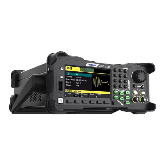
Brief Introduction HDG3000 series waveform generator is an economical, high performance, multi-functional dual channel function/arbitrary waveform generator that does integrates functions of function generator, arbitrary waveform generator, pulse generator, harmonic generator, analog/digital modulator, counter, etc. Features: The six maximum output frequencies are 100MHz, 80MHz, 60MHz, 40MHz, 25MHz and 15MHz. - Page 10 Model CH1/CH2 Model Channels Max.Frequency Sampling Rate Sampling Rate HDG3012B 15MHz 300MS/s HDG3022B 25MHz 300MS/s HDG3042B 40MHz 300MS/s HDG3062B 60MHz 300MS/s HDG3082B 80MHz 300MS/s HDG3102B 100MHz 300MS/s HDG3013C 15MHz 300MS/s 150MSa/s HDG3023C 25MHz 300MS/s 150MSa/s HDG3043C 40MHz 300MS/s 150MSa/s HDG3063C 60MHz 300MS/s 150MSa/s...
-
Page 11: Chapter 1 Quick Start
Chapter 1 Quick Start This chapter introduces the front panel, rear panel, user interface and parameter setting method as well as precautions when using the instrument for the first time. General Inspection Front Panel Rear Panel Prepare Instrument for Use ... -
Page 12: General Inspection
1.1 General Inspection Please check the instrument as following steps after receiving an oscilloscope: Check the shipping container for damage: Keep the damaged shipping container or cushioning material until the contents of the shipment have been checked for completeness and the instrument has been checked mechanically and electrically. - Page 13 parameters. Mod: Enablegenerate modulated waveforms.A variety of analog and digital modulation methods are provided to generate AM, DSB-AM, FM, PM, ASK, FSK, PSK, BPSK, QPSK, 3FSK, 4FSK, OSK and PWM modulation signals. Sweep: Enable generate sweep signals of "sine", "square", "ramp", "pulse", "harmonic" and "arbitrary (except DC)".
-
Page 14: Rear Panel
and then press the button you need to get the help information for. 12. USB HOST Interface External storage device (USB disk) can be accessed for saving or loading settings files.The file system format of the external storage device is FAT32 and the memory is no more than 32G. - Page 15 3. CH3 Output Connector BNC connector with 50Ω nominal output impedance. When CH3 output is turned on (press [CH1/2/3] to select the CH3 window display, then press CH3 softkey and switch to "ON"), the corresponding connector outputs the configured waveform. 4.
-
Page 16: Prepare Instrument For Use
1.4 Prepare Instrument for Use Adjust the Handle To adjust the handle of the instrument, hold both sides of the handle and pull them outward, then rotate the handle. Connect to AC power cord Connect the power cord as required. This instrument can accept the power supply of 100-120VAC (±10%), 45-440 Hz or 120-240VAC (±10%), 45-66Hz. -
Page 17: The User Interface
To turn off the instrument, press the power switch. 1.5 The User Interface Theuser interface is shown in the following figure. 1. Displays the selected channel.Only HDG3000C supports CH3 output. 2. Channel Parameters Display the waveform parameters of the current channel. Press the parameter softkey and use the numeric keypad or direction keys and knob to modify the value. -
Page 18: Parameter Setting Method
1.6 Parameter Setting Method Users can use the numeric keypad or knob and direction keys to set parameters. 1.6.1 Numeric Keypad The numeric keypad consists of the following parts: Number keys The 0 to 9 number keys are used to directly input the desired parameter value. Decimal point Press this key to insert a decimal point "."... -
Page 19: Help
edited. During filename edit, use the direction keys to move the cursor. Functions of the knob: When the parameter is in editable state, turn the knob to increase (clockwise) or reduce (counterclockwise) the parameter with specified step. During filename edit, use the knob to select the characters in the soft keyboard. ... -
Page 20: Chapter 2 Basic Waveform Output
Chapter 2 Basic Waveform Output HDG3000B(C) can output basic waveforms (including Sine, Square, Ramp, Pulse and Noise) from one of the channels separately or from the two channels at the same time.At start-up, the channel is configured as a sine waveform with 1KHz frequency and 200mVpp amplitude by default. -
Page 21: Select The Channel
2.1 Select the Channel Users can configure HDG3000B(C) to output basic waveform from a single channel or from dual channels at the same time. Please select the desired channel before configuring waveform parameters. At start-up, CH1 is selected by default. Press [CH1/2] or [CH1/2/3] button on the front panel and the corresponding area in the user interface is illuminated. -
Page 22: Set The Amplitude
2.2.3 Set the Amplitude The amplitude range is limited by Frequency or Period and Impedance settings. Please refer to "Output Characteristics" in "Specifications". The default value is 200mVpp. The amplitude displayed on the screen is the default value or the amplitude previously set. When the instrument configuration (e.g. -
Page 23: Set The Start Phase
Press [Setting] >Offsetsoftkey.At this point, use the numeric keypad to enter the offset value and select the desired unit from the pop-up unit menu, or use the direction keys and knob to modify the current value. 1. For the input method of offset value, refer to the introduction in "Parameter Setting Method". -
Page 24: Set The Duty Cycle
After synchronizing phase: 2.2.6 Set the Duty Cycle Duty cycle is defined as the percentage that the high level takes up in the whole period as shown in the figure below. The duty cycle range is limited by the "Frequency/Period" setting. Please refer to "Signal Characteristics"... -
Page 25: Set The Pulse Parameters
Symmetry can be set in the range of 0% to 100%.The default value is 50%. Press [Wave] >Rampsoftkey to select the rampwave function and press Symmetrysoftkey to highlight it.At this point, use the numeric keypad to input the value and select the unit "%" from the unit menu that pops up, or use the direction keys and the knob to modify the current value.For the input method of symmetry value, refer to the introduction in "Parameter Setting... -
Page 26: Enable The Channel Output
period. The pulse width and pulse duty cycle are correlative. Once a parameter is changed, the other will be automatically changed. The pulse duty cycle is limited by the "Minimum Pulse Width" and "Pulse Period". P uls e Duty C ycle Minim um P uls e Width ÷... -
Page 27: Basic Waveform Output Example
2.3 Basic Waveform Output Example Configure the generator to output a pulse waveform with 1.5MHz frequency, 500mVpp amplitude, DC offset, 200ns pulse width, 75ns leading edge time and 100ns trailing edge time. 1. Press [CH1/2/3] button on the front panel and select CH1.The corresponding area of CH1 in the user interface is illuminated. - Page 28 User Manual...
-
Page 29: Chapter 3 Arbitrary Waveform Output
Chapter 3 Arbitrary Waveform Output HDG3000B(C) can output the built-in waveforms and user-defined arbitrary waveforms from a single channel or from two channels at the same time.The 160 kinds of built-in waveforms are stored in the internal non-volatile memory. The user-defined arbitrary waveforms can contain 64 to 2M data points. -
Page 30: Enable Arbitrary Waveform
3.1 Enable Arbitrary Waveform Press [Wave] >Arb softkey to enable the arbitrary waveformfunction and open the operation menu of thearbitrary waveform. To set the basic parameters of arbitrary waveforms, refer to “Set the Parameters”. Type: Select the built-in waveforms or user-defined arbitrary waveform stored in external storage. 3.2 Select Arbitrary Waveform The HDG3000B(C) allows the user to select arbitrary waveform in the internal or external memory of the instrument for output. - Page 31 SineVer Sine-Ver waveform StairDn Stair-down waveform StairUD Stair-up and stair-down waveform StairUp Stair-up waveform Trapezia Trapezoid waveform Project BandLimited Bandwidth-limited signal BlaseiWave Time-velocity curve of explosive vibration Butterworth Butterworth filter Chebyshev1 Chebyshev1 filter Chebyshev2 Chebyshev2 filter Combin Combination function CPulse C pulse CWPulse CW pulse...
- Page 32 Medical LFPulse Waveform of the low frequency pulse electrotherapy Tens1 Waveform 1 of the nerve stimulation electrotherapy Tens2 Waveform 2 of the nerve stimulation electrotherapy Tens3 Waveform 3 of the nerve stimulation electrotherapy Standard Ignition Ignition waveform of the automotive motor ISO16750-2 SP Automotive starting profile with ringing ISO16750-2 VR...
- Page 33 ARB_X2 Square function Trigonome CosH Hyperbolic cosine CosInt Integral cosine Cotangent CotHCon Concave hyperbolic cotangent CotHPro Protuberant hyperbolic cotangent CscCon Concave cosecant CscPro Protuberant cosecant CscHCon Concave hyperbolic cosecant CscHPro Protuberant hyperbolic cosecant RecipCon Concave reciprocal RecipPro Protuberant reciprocal SecCon Concave secant SecPro Protuberant secant...
- Page 34 BlackmanH BlackmanH window BohmanWin Bohman window Boxcar Rectangle window ChebWin Chebyshev window FlattopWin Flat Top weighted window Hamming Hamming window Hanning Hanning window Kaiser Kaiser window NuttallWin Nuttall-defined minimum 4-term Blackman-Harris window ParzenWin Parzen window TaylorWin Taylor window Triang Triangle window (Fejer window) TukeyWin Tukey (tapered cosine) window User-definedWaveforms...
-
Page 35: Chapter 4 Harmonic Output
Chapter 4 Harmonic Output The HDG3000B(C) can be used as a harmonic generator to output harmonic with specified order, amplitude and phase. It is usually used in the test of harmonic detector device or harmonic filter device. This chapter introduces how to configure the generator to output harmonics. Subjects in this chapter: ... -
Page 36: Overview
4.1 Overview According to Fourier transform, time domain waveform is the superposition of a series of sine waveforms as shown in the equation below: Generally, component with frequency is called basic waveform, is basic waveform frequency, φ is basic waveform amplitude and is basic waveform phase. -
Page 37: Set The Harmonic Type
4.4 Set the Harmonic Type HDG3000B(C) can output even harmonics, odd harmonics or all orders of harmonics.Press[Wave] >Harmonicsoftkey on the front panel to enter the harmonic setting menu, and press Type softkey to select the desired harmonic type. 1. Even Select this type and the instrument would output basic waveform and even harmonics. -
Page 38: Chapter 5 Modulation
Chapter 5 Modulation HDG3000B(C) supports AM, DSB-AM, FM, PM, 2ASK, 2FSK, 2PSK, BPSK, QPSK, 3FSK, 4FSK, OSK and PWM modulations. It can output modulated waveform from a single channel or from two channels at the same time. The modulated waveform consists of carrier waveform and modulating waveform. -
Page 39: Ammodulation
5.1 AMModulation A modulated waveform consists of a carrier waveform and a modulating waveform. In AM, the carrier amplitude is varied by the voltage level of the modulating waveform. 5.1.1 Select AM Modulation Press [Mod] >Type > AMsoftkey to enable AM function. ... -
Page 40: Modulation Frequency
External Source When external modulation source is selected, the Frequency and Shape menu in the modulation menu is grayed out and disabled.The instrument receives the external modulation signal from the [FSK/Trig/Sync/Extmod] connector on the rear panel.At this point, the AM modulation amplitude is controlled by the ±4V signal level on this connector.For example,when the modulation depth is 100%, the output amplitude is maximum when the external modulation signal is +4V, and the output amplitude is the minimum when the external modulation signal is -4V. -
Page 41: Select Dsb-Am Modulation
5.2.1 Select DSB-AM Modulation Press [Mod] >Type > DSB-AMsoftkey to enable DSB-AM function. When Mod is enabled, Sweep or Burst will be disabled automatically. After DSB-AM is enabled, the instrument will generate DSB-AM waveform with the currently specified carrier and modulating waveforms. To avoid multiple waveform changes, enable modulation after configuring the other modulation parameters. -
Page 42: Modulation Frequency
100%, the output amplitude is maximum when the external modulation signal is +4V, and the output amplitude is the minimum when the external modulation signal is -4V. Other Channels CH1 and CH2 can be used as modulation sources reciprocally. When CH1 is used as the modulated wave, CH2 can be used as the modulation source. -
Page 43: Select Fm Modulation
5.3.1 Select FM Modulation Press [Mod] >Type > FMsoftkey to enable FM function. When Mod is enabled, Sweep or Burst will be disabled automatically. After FM is enabled, the instrument will generate FM waveform with the currently specified carrier and modulating waveforms. -
Page 44: Modulation Frequency
Other Channels CH1 and CH2 can be used as modulation sources reciprocally. When CH1 is used as the modulated wave, CH2 can be used as the modulation source. And vice versa. When selecting another channel as the modulation source, please turn on the output of that channel. -
Page 45: Select Pm Modulation
5.4.1 Select PM Modulation Press [Mod] >Type >PMsoftkey to enable PM function. When Mod is enabled, Sweep or Burst will be disabled automatically. After PM is enabled, the instrument will generate PM waveform with the currently specified carrier and modulating waveforms. To avoid multiple waveform changes, enable modulation after configuring the other modulation parameters. -
Page 46: Modulation Frequency
Other Channels CH1 and CH2 can be used as modulation sources reciprocally. When CH1 is used as the modulated wave, CH2 can be used as the modulation source. And vice versa. When selecting another channel as the modulation source, please turn on the output of that channel. -
Page 47: Carrier Waveform Shape
carrier and modulating waveforms. To avoid multiple waveform changes, enable modulation after configuring the other modulation parameters. 5.5.2 Carrier Waveform Shape ASK carrier shape: Sine (default), Square, Ramp, Pulse, Arbitrary (except DC) or Harmonic waveform. Press[Wave] button on the front panel to select the desired carrier waveform. ... -
Page 48: Modulation Amplitude
5.5.6 Modulation Amplitude After enabling ASK modulation function, press [Mod]>Amplitudesoftkey to set the modulation amplitude. Use the numeric keypad or direction keys and knob to input the desired amplitude value. The range of amplitude (HighZ) is from 2mV to 20V and the default is 100mV. 5.6 FSK Modulation Users can configure the instrument to "shift"... -
Page 49: Fsk Rate
Internal Source When internal modulation source is selected, the modulating waveform is set as a Square with 50% duty cycle, and the rate at which the output frequency "shifts" between "carrier frequency" and "modulating frequency" is determined by "FSK Rate". External Source When external modulation source is selected, the generator receives the external modulating signal from the[FSK/Trig/Sync/Extmod] connector on the rear panel. -
Page 50: Carrier Waveform Shape
5.7.2 Carrier Waveform Shape PSK carrier shape: Sine (default), Square, Ramp, Pulse, Arbitrary (except DC) or Harmonic waveform. Press [Wave] button on the front panel to select the desired carrier waveform. Noise and DC could not be used as carrier waveform. 5.7.3 Carrier Waveform Phase Press[Setting] >Phasesoftkey on the front panel and use the numeric keypad or direction keys and knob to input the desired phase. -
Page 51: Bpsk Modulation
5.8 BPSK Modulation Users can configure the instrument to "shift" its output phase between two preset values using BPSK modulation. The rate at which the output shifts between the two phases (called the "carrier phase" and the "modulation phase") is determined by the internal signal level of the instrument. 5.8.1 Select BPSK Modulation Press [Mod] >Type >... -
Page 52: Modulation Phase
5.8.6 Modulation Phase Pressing [Mod]>Phasesoftkey to set the modulation phase. Use the numeric keypad or direction keys and knob to input the desired pahse values. The phase range is from 0º to 360º and the default is 180º. 5.9 QPSK Modulation Users can configure the instrument to "shift"... -
Page 53: Qpsk Rate
5.9.5 QPSK Rate When internal modulation source is selected, press [Mod] > Rate softkey to set the rate at which the output phase shifts between "carrier phase" and three "modulation phases". Use the numeric keypad or direction keys and knob to input the desired rate value. ... -
Page 54: Modulation Source
Press [Setting] > Frequency softkey on the front panel, and then use the numeric keypad or direction keys and knob to input the desired frequency value. 5.10.4 Modulation Source 3FSK uses internal modulation source. The modulating waveform is square. 5.10.5 3FSK Rate When internal modulation source is selected, press [Mod] >... -
Page 55: Carrier Waveform Frequency
5.11.3 Carrier Waveform Frequency For different carrier waveforms, the settable range of carrier frequency is different. please refer to "Frequency Characteristics" in "Specifications".The default value is 1kHz. Press [Setting] > Frequency softkey on the front panel, and then use the numeric keypad or direction keys and knob to input the desired frequency value. -
Page 56: Select Osk Modulation
5.12.1 Select OSK Modulation Press [Mod] >Type > OSKsoftkey to enable OSK function. When Mod is enabled, Sweep or Burst will be disabled automatically. After OSK is enabled, the instrument will generate OSK waveform with the currently specified carrier and modulating waveforms. -
Page 57: Osk Rate
External Source When external modulation source is selected, the signal generator receives the external modulation signal from the [FSK/Trig/Sync/Extmod] connector on the rear panel. 5.12.5 OSK Rate When internal modulation source is selected, press [Mod] > Rate softkey to set. ... -
Page 58: Carrier Waveform Duty
5.13.3 Carrier Waveform Duty Press [Wave] > Squaresoftkey select square carrier waveform. Press [Setting] >Dutysoftkey, then input the required value through the numeric keypad or knob. 5.13.4 Modulation Source Press [Mod] > Signal Source softkey to select Internal, External or Another Channel as the modulation source. -
Page 59: Duty Deviation
5.13.6 Duty Deviation Press[Mod]>deviationsoftkey and input the desired value using the numeric keypad or direction keys and knob. Duty deviation represents the variation (in %) of the modulated waveform Duty relative to the original pulse Duty. Duty deviation range: 0.1% to 49.9%. ... -
Page 60: Chapter 6 Sweep
Chapter 6 Sweep In sweep mode, the instrument outputs the waveform that changes from the start frequency to the stop frequency at a specified sweep rate.HDG3000B(C) supports linear sweep mode. Users can configure the instrument to output one sweep from start frequency to stop frequency by applying an external or manual trigger. -
Page 61: Select Sweep
6.1 Select Sweep Press[Sweep] button on the front panel to enable the Sweep function (the backlight of the key goes on), and Mod or Burst function will be automatically disabled (if currently enabled). To avoid multiple waveform changes, enable the sweep mode after configuring the other parameters (as waveforms and amplitudes of basic waves). -
Page 62: Linear Sweep
Define the minimum frequency of the waveform currently selected as Fmin, the maximum frequency as Fmax and Fm = (Fmin+Fmax)/2. The range of center frequency is from Fmin to Fmax.For frequency parameters of different waveforms, please refer to "Frequency Characteristics" in "Specifications". The range of the frequency span is influenced by the center frequency: Center frequency <Fm: frequency span range is ±2 ×... -
Page 63: Hold Time
6.7 Hold Time The hold time specifies how long time the waveform stays at the stop frequency. When [Sweep] is enabled, press the Hold Time softkey and use the numeric keyboard or knob to change the hold time. The default value is 1s and the settable range is from 1ms to 50Ks. 6.8 Mark Frequency When the output signalfrequency is less than the specified mark frequency, there will output the low level signal from the[FSK/Trig/Sync/Extmod] connector on the rear panel.When the output... - Page 64 levelsignal from the [FSK/Trig/Sync/Extmod] connector on the rear panel. When the output signal frequency is at or greater than the specified mark frequency, the signal outputs on the [FSK/Trig/Sync/Extmod] connector will change from low level to high level. External Trigger: The [FSK/Trig/Sync/Extmod] connector is used as the input terminal of external trigger signal and has no trigger output.
-
Page 65: Chapter 7 Burst
Chapter 7 Burst The HDG3000B(C) can output a waveform for a specified number of cycles, called a burst. It supports control of burst output by internal, external or manual trigger source; supports three kinds of burst types including N cycle, Infinite cycle and Gated. Burst is allowed with sine, square, ramp, pulse, Harmonic, noise (allowed only in gated burst mode) or arbitrary waveforms (except DC). -
Page 66: Selectburst
7.1 SelectBurst Press[Burst] button on the front panel to enable Burst function (the backlight of the key goes on),and Mod or Sweep function will be automatically disabled (if currently enabled). To avoid multiple waveform changes, enable burst mode after configuring other parameters. 7.2 Burst Type This instrument could output three types of bursts, including N Cycle, Infinite Cycle and Gate. - Page 67 outputs a continuous waveform after receiving trigger signal. Press [Burst] >Type softkey to select “Inf Cycle”.A schematic diagram of infinite cycle pulse will be displayed on the screen. For Infinite Cycle mode, the trigger source includes "Internal", "External" or "Manual". Besides, users can set the "Phase", "Count"...
-
Page 68: Burstcount
waveform, the output will stop immediately once the gated signal becomes "False". Gated Burst could only be triggered by External trigger source. In addition, users can set the "Phase". 7.3 BurstCount Burst count is the number of carrier waveforms in one burst period. It is only available forN CycleBurst mode (internal, external, or manually trigger sources). -
Page 69: Gatepolarity
default setting is "Internal". Internal Trigger When internal trigger is selected, the generator can only output N cycle burst and the burst frequency is determined by the "Burst Period". External Trigger When external trigger is selected, the generator can output N cycle, infinite or gated burst. The generator receives the trigger signal from the[FSK/Trig/Sync/Extmod] connector on the rear panel. -
Page 70: Chapter 8 Counter
Chapter 8 Counter The generator provides a counter which can measure various parameters (such as frequency, period, duty cycle, positive pulse width and negative pulse width) of external input signal. Press[Utility] >Countersoftkey on the front panel to enablecounter function.Input the singal to the Counter connector on the rear panel measure. -
Page 71: Chapter 9 Store
Chapter 9 Store The instrument allows the user to store the current settings state of the instrument in internal or external storage and recall it when needed. 9.1 Store System The instrument provides an internal memory (home disk) and an external memory (USB disk). Home disk: Users can save the instrument settings state to this disk in.pho format. - Page 72 New File In Store interface, rotate the knob to select home disk or usb disk, and then press New softkey to enter the filename editing interface, as shown in the figure below. Filename Input Area Virtual Soft Keyboard 1. Press Type softkey to select "File". File: Create a new state file.
- Page 73 Rename Use the knob to select the specified file or directory and press Rename softkey to rename. Refer to the operation method of creating a new file. After the completion of the denominate, press Confirm softkey to confirm the change. Delete Use the knob to select the specified file or directory and press Delete softkey to delete the selected file or directory.
-
Page 74: Chapter 10 Utility
Chapter 10 Utility The signal generator allows the user to configure channel parameters, configure remote interfaces, and set system parameters. Sync Impedance Settings System Settings Firmware Update User Manual... -
Page 75: Sync
10.1 Sync The synchronous signal is output from the [FSK/Trig/Sync/Extmod] connector on the rear panel. The instrument could output the sync signals of basic waveforms (except Noise), arbitrary waveforms (except DC), Harmonics, Sweep, Burst and Modulation from a single channel or two channels at the same time. -
Page 76: Impedance Settings
selected, there is no sync signal output. 10.2 Impedance Settings The Impedance setting affectsthe output amplitude and DC offset voltage.For the front panel [1] connector, the HDG3000B(C) has a fixed series output impedance of 50Ω.If the actual load is different from the specified value, then the displayed voltage level will not match the voltage level of the components under test. -
Page 77: System Settings
10.3 System Settings 10.3.1 Language The signal generator supports Chinese and English menu, and provides corresponding help information, prompt information and interface display. Press [Utility] > Languagesoftkey to select the desired language.When "Chinese" or "English" is selected, the menu, help message, prompt message, and interface are displayed in Chinese or English, respectively. -
Page 78: Power On Settings
10.3.3 Power On Settings Set the configuration to be used when the instrument is powered on the next time to Default, Last or Output off. The default setting is "Default". Default: Denote the factory default settings except some parameters (such as: Language). ... -
Page 79: Firmwareupdate
Then enter the interface that you need to save, andpress[Utility] button, the instrument completes the screenshot and enters the Utility menu. At this time, the signal generator has cached the screenshot inside the instrument.PressSavePicsoftkey, and the instrument will save the screenshot to the USB stick. -
Page 80: Chapter 11 Remote Control
Chapter 11 Remote Control The HDG3000B(C) can be controlled remotely through the following two mothods. Use PC software Users can use the PC software to send commands to remotely control the instrument. You can download the software from our official website. User-defined programming Users can program and control the instrument by using the SCPI (Standard Commands for Programmable Instruments) commands. -
Page 81: Install Keysight Io Libraries Suite
11.1 Install Keysight IO libraries suite Users can download the application software package on the official website of Hantek: http://hantek.com/products/detail/17187 Or click the following website to download latest one: http://www.keysight.com/main/software.jspx?ckey=2175637&id=2175637&nid=-11143.0.00&l c=eng&cc=GB Double click the icon to start installing. Click ‘Next’ to continue. - Page 82 Select a Typical and click ‘Next’ to continue. Or select a Custom and click ‘Next’ to continue. User Manual...
- Page 83 Select “Install Keysight VISA as primary VISA” and click ‘Next’ to continue. Click ‘Install’ to start copying files. User Manual...
- Page 84 The installation is completed automatically. You will see the running IO program in the lower right corner of the screen. User Manual...
-
Page 85: Remote Control Via Usb
For example, HDG3102C(USB0::0x0483::0x5740::************::0::INSTR) 4. Control the instrument remotely 1) Use PC software Users can download the application software package on the official website of Hantek: http://hantek.com/products/detail/17187 Double-click the Setup.exe file and install it according to the installation wizard. After the installation is complete, the software icon will be displayed on the computer desktop. - Page 86 2) User-defined programming Start up Keysight IO and the software will automatically search for the instrument resource currently connected to the PC. Click “Send Commands To This Instrument” to open Keysight interactive IO interface.You can send commands and read data. For more information about the commands and programming, refer to the SCPI protocol manual.
-
Page 87: Appendix A Specifications
Appendix A Specifications All technical specifications are suitable for HDG3000B(C) series signal generators.Unless otherwise stated, all technical specifications are guaranteed upon the following two conditions. The signal generator is in the calibration period. The signal generator has operated continuously for more than 30 minutes at the specified operating temperature (18℃... - Page 88 Ramp Characteristics ≤ 1% of peak output (typical, 1kHz, 1Vpp, symmetry 100%) Linearity Symmetry 0% ~ 100% Pulse Characteristics Period 67ns~1Ms 67ns~1Ms 67ns~1Ms 67ns~1Ms 67ns~1Ms 67ns~1Ms ≥16ns Pulse 0.001%~99.999%; Duty Cycle Range varies with frequency ≥9ns Rise/Fall time Typical (1kHz, 1Vpp) Overshoot ≤5% Arbitrary Wavefrom Generator...
- Page 89 Vpp, mVpp, Vrms, dBm (50Ω terminal) Unit Resolution 1mVpp Offset Characteristics (50Ω terminal) Range ±5Vpkac+dc Accuracy ±(1% of setting value + 5mV + 1% of amplitude) Waveform Output 50Ω Impedance Modulation Characteristics Modulation AM, DSB-AM, FM, PM, ASK, FSK, PSK, BPSK, QPSK, 3FSK, 4FSK, OSK, Type Carrier Sine, Square, Ramp, Pluse, Harmonic, Arb.
- Page 90 Frequency Carrier Sine, Square, Ramp, Pluse, Harmonic, Arb. (except DC) Waveforms Modulation Internal, External, another channel Source Modulation Sine, Square, Ramp, Noise, Sinc, Exp Fall, Haver Sine, Lorentz, Gause, Dual Waveforms Tone, ECG Modulation 2mHz~1MHz Frequency Phase 0 ° ~ 360 ° Deviation Carrier Sine, Square, Ramp, Pluse, Harmonic, Arb.
- Page 91 Rate 2mHz~1MHz QPSK Carrier Sine, Square, Ramp, Pluse, Harmonic, Arb. (except DC) Waveform Modulation PN15, PN21 Data Source Rate 2mHz~1MHz 3FSK Carrier Sine, Square, Ramp, Pluse, Harmonic, Arb. (except DC) Waveform Modulation Internal Source Modulation 50% duty cycle square wave Waveforms Rate 2mHz~1MHz...
- Page 92 AM, DSB-AM, FM, PM, OSK, PWM: 75MVRMS ~ ± 5VAC + DC Input Range ASK, FSK, PSK: TTL level Input 50KHz Bandwidth Input 10kΩ Impedance Sweep Characteristics Carrier Sine, Square, Ramp, Pluse, Harmonic, Arb. (except DC) Waveform Type Linear Type Direction Up Sweep Time 1ms ~ 50Ks Hold/Return...
- Page 93 Pulse width >100ns Trigger Output Level TTL - compatible Pulse Width >60ns Maximum 1MHz Rate Clock Reference External Reference Input Lock Range 10 MHz + 50 Hz Level Low level: 0~400mV, high level: 2.5V~ 5V Locking Time <2s 50Ω, DC coupling Impedance Internal Reference Output Frequency...
-
Page 94: Appendix B Accessories
50Ω Impedance General Specifications Interface USB Host, USB Device Display 4.3-inch color TFT LCD screen 100-120VAC (±10%),45Hz to 440Hz, CATⅡ Power Voltage 120-240VAC (±10%),45Hz to 66Hz, CATⅡ Power <30W Consumption Fuse T, 0.5A, 250V, 5x20mm Environment Temperature Operating: 0℃ ~ 45℃ Range Non-operating: -20℃...
Need help?
Do you have a question about the HDG3000BC Series and is the answer not in the manual?
Questions and answers