
Related Manuals for SMC Networks D-MP Series


Summary of Contents for SMC Networks D-MP Series
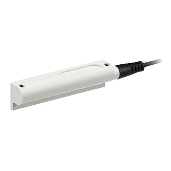
- Page 1 No.D-※S-OMU0002-A PRODUCT NAME Actuator Position Sensor MODEL / Series / Product Number D-MP# series...
-
Page 2: Table Of Contents
Table of Contents Safety Instructions Model Indication and How to Order Summary of Product parts Mounting and Installation Installation Wiring Setting IO-Link Troubleshooting Maintenance Specifications Dimensions No.D-※S-OMU0002-A... -
Page 3: Safety Instructions
Safety Instructions These safety instructions are intended to prevent hazardous situations and/or equipment damage. These instructions indicate the level of potential hazard with the labels of "Caution", "Warning" or "Danger". They are all important notes for safety and must be followed in addition to International Standards (ISO/IEC) , and other safety regulations. - Page 4 Safety Instructions Caution 1.The product is provided for use in manufacturing industries. The product herein described is basically provided for peaceful use in manufacturing industries. If considering using the product in other industries, consult SMC beforehand and exchange specifications or a contract if necessary. If anything is unclear, contact your nearest sales branch.
- Page 5 Operator This operation manual is intended for those who have knowledge of machinery using pneumatic equipment, and have sufficient knowledge of assembly, operation and maintenance of such equipment. Only those persons are allowed to perform assembly, operation and maintenance. Read and understand this operation manual carefully before assembling, operating or providing maintenance to the product.
- Page 6 The description "Cylinder" or "actuator" indicates a cylinder, air gripper, rotary actuator, electrical actuator or cylinder, etc. Hereafter the "actuator position sensor" is described as the "position sensor". Design and Selection Warning (1) Review the specifications. If the product is used with an excessive load or used outside of the specifications, it may cause damage or malfunction.
- Page 7 (9) Install a rotation stopper to the actuator piston rod. Use a guide or select an SMC product with a rotation stopping function. The accuracy may decrease without a rotation stopper. With some cylinders, the magnet may rotate even when the piston rod does not rotate. The magnet inside some cylinders with guide may rotate.
- Page 8 Operating Environment Warning (1) Do not use the auto switch in the presence of explosive gases. Position sensors are not designed with an explosion proof construction. Fire or an explosion may result. Caution (1) Do not use in a location where magnetic fields are generated. The Position sensor will malfunction or the accuracy will be decreased.
-
Page 9: Model Indication And How To Order
Model Indication and How to Order D-MP Measuring range Lead wire Symbol Content Symbol Content 25 mm 2,000 mm 50 mm M8 4-pin, plug connector: 0.3 m 100 mm M12 4-pin A-coded, plug connector: 0.3 m Class A 200 mm Summary of Product parts ○Summary of parts Lead wire... - Page 10 Display Indicator Indicator Category Mode Description light 2 light 1 Current Analogue current output active output Analogue output Voltage Analogue voltage output active output System status IO-Link IO-Link connection active Sensor not ready for operation/ Error Detectable magnetic field is decrease LED flashing at 4 Hz Switch output High High...
-
Page 11: Mounting And Installation
Mounting and Installation ■Installation When mounting an actuator position sensor, use a mounting bracket appropriate for the cylinder/actuator. The mounting method differs according to the type of actuator and the inner diameter of the tube. When mounting a sensor for the first time, check that the cylinder/actuator has a built-in magnet and use an appropriate bracket for the cylinder/actuator. -
Page 12: Wiring
■Wiring SIO mode NPN output PNP output Brown (No.1) Brown (No.1) Load Black (No.4) Black (No.4) White (No.2) Load White (No.2) Power supply Power supply 15 to 30 VDC 15 to 30 VDC Load Blue (No.3) Load Blue (No.3) Connector pin numbers shown in brackets. IO-Link mode Brown (No.1) Black (No.4) -
Page 13: Setting
Setting Initial settings are as follows: Switch output: Low (NPN = ON, PNP = OFF), Analogue output: current output, Range: full range Teach pad setting procedure Note: For teaching the measurement range, make sure that the piston position is at the start point of the range. Click the teach pad, and then click and hold down the teach pad. - Page 14 Teach level 2 When a magnet (subject to be detected) is present outside of the measurement range, the indicator LED flashes 4 times and setting is complete. -13- No.D-※S-OMU0002-A...
- Page 15 ○Analogue output Voltage [V] Current [mA] Set measuring range Set measuring range ●Analogue output function •Measuring range can be changed by setting. •Whole measuring range can be reset using the reset function. •Analogue current output and analogue voltage output can be selected. •Analogue output can be reversed.
- Page 16 ○Switch output mode ●There are 4 modes for switch output. Follow the conditions below. •SP1 + Hysteresis < Measuring range •SP2 + Hysteresis < Measuring range •SP1-Hysteresis >0 •SP2-Hysteresis > 0 (1) Single switch point mode Normal output Reversed output (2) Auto switch mode Normal output Reversed output...
-
Page 17: Io-Link
IO-Link ○Communication function This product can check the position measurement value, diagnostic information and switch output status using cyclic data communication via the IO-Link system. ○Data storage function The data storage function stores the IO-Link device parameter settings to the IO-Link master. With the IO-Link data storage function, the IO-link device can be replaced easily without re-setting the equipment construction or setting parameters. - Page 18 IO-Link parameter settings ○IODD file IODD (I/O Device Description) is a definition file which provides all properties and parameters required for establishing functions and communication of the device. IODD includes the main IODD file and a set of image files such as vendor logo, device picture and device icon.
- Page 19 ○Service data The tables below indicates the parameters which can be read or written by simple access parameter (direct parameters page) and ISDU parameters which are applicable to various parameters and commands. •Direct operation parameters Address Access Parameter name Default (decimal number) Value 0x07 Vendor ID...
- Page 20 •System command (Index 2) In the ISDU index 0x002 SystemCommand (system command), the command shown in the table below will be issued. The button of each system command is displayed on the IO-Link setting tool. Click the button to send the system command to the product. Command Command name Evaluation method...
- Page 21 •Product individual parameters Index Access Initial Selection range (decimal Subindex Parameter name Format Length 1 2 value Value/Range number) 3 3 SetPoint1 bit(16) 16 bit 0x003C BDC1 3 3 (60) SetPoint2 bit(0) 16 bit 4 Logic bit(24) 8 bit 0x003D 5 BDC1 Mode...
- Page 22 •Product individual parameters 2 Index Access Initial Selection range (decimal Subindex Parameter name Format Length value Value/Range number) 0: default BDC = BDC1 1: BDC1 0x3A 2: BDC2 Teach-in channel 8 bit (58) 3: BDC3 4: BDC4 5: Measuring range 0x3B Teach-in status...
- Page 23 Initial value and selection range Initial value Initial value Selection range Product No. Parameter (value) (mm) Value/Range Setpoint 1 (SP1) 12.5 mm D-MP025 Setpoint 2 (SP2) 11.5 mm 0 to 500 Measuring range 0 to 500 25 mm Setpoint 1 (SP1) 25 mm D-MP050...
-
Page 24: Troubleshooting
Troubleshooting When any position sensor failure occurs, perform the following trouble shooting. A failure of the position sensor might depend on the operating environment (application etc.) and may need to be tested separately by contacting SMC. Incorrect Is the actuator Does not operate application applicable? - Page 25 Teach pad operation Trouble No.7 is not possible IO-Link LED IO-Link does not Trouble No.8 do not flash function correctly Trouble No.9 Trouble No.10 -24- No.D-※S-OMU0002-A...
- Page 26 •Cross-reference for troubleshooting Trouble Problem Possible cause Investigation method Countermeasures •The Auto switch Setting mode output does not (hysteresis, switch output Incorrect setting Reset the functions turn off mode, normal output/reversed The operation output) LED does not turn off The presence of the following Improper setting conditions Reset the position sensor,...
- Page 27 Trouble Problem Possible cause Investigation method Countermeasures Incorrect wiring Check the output wiring. Correct the wiring The output does Check the repeated bending Correct the wiring Breakage of lead not turn on stress/tension applied to a part (Correct the tensile force and The operation wire of the lead wire.
- Page 28 Trouble Problem Possible cause Investigation method Countermeasures If the teach pad is touched Local user Unlock the interface in IO- while locking, the green LED interface is locked Link mode. flashes 4 times. Not entered into Teach pad the transition The teach pad is continuously Touch the teach pad after 3 operation is not...
-
Page 29: Maintenance
Maintenance How to reset the product after a power cut or when the power has been unexpectedly removed Regarding set up, contents of the program may be maintained by customer's application systems. Be sure to confirm safety when returning operation of the cylinder and actuator because it could have been stopped in an unstable condition. -
Page 30: Specifications
Specifications Model D-MP025 D-MP050 D-MP100 D-MP200 Measuring range 25 mm±1 mm 50 mm±1 mm 100 mm±1 mm 200 mm±1 mm 15 to 30 VDC, ripple (p-p) 10% or below Power supply voltage (with power supply polarity protection) Current consumption 48 mA or less (when no load is applied) 1 2 Repeatability 0.1 mm (@25... -
Page 31: Dimensions
■Dimensions Teach pad Indicator light Mounting thread D-MPA M8-4 pin connector D-MPB M12-4pin connector D-MPC (mm) Model Detectable range D-MP025 40.5 D-MP050 64.9 D-MP100 114.9 D-MP200 214.7 -30- No.D-※S-OMU0002-A... - Page 32 Revision history A: Contents revised in several places [June 2019] 4-14-1, Sotokanda, Chiyoda-ku, Tokyo 101-0021 JAPAN Tel: + 81 3 5207 8249 Fax: +81 3 5298 5362 https://www.smcworld.com Note: Specifications are subject to change without prior notice and any obligation on the part of the manufacturer. ©...
Need help?
Do you have a question about the D-MP Series and is the answer not in the manual?
Questions and answers