Advertisement
Quick Links
Instructions for installing the 9700/12-9700
Surface Vertical Rod Exit Device
FOR ASSISTANCE, CALL SARGENT AT 1-800-727-5477 or www.sargentlock.com
CAUTION: CHECK BEFORE STARTING DOOR PREP
Door should be fitted and hung. Check box label for size of exit device, function, hand and design.
Surface of the door must be flush. Clear away
any raised projections to allow exit device to rest
on flat surface of the door.
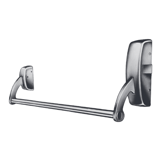
THIS EXIT DEVICE IS NON-HANDED
OUT
Right hand
reverse bevel
Bracket
cover
Cross bar plug
Left hand
reverse bevel
Bracket
chassis
Cross bar
Copyright © 2009, Sargent Manufacturing Company, an ASSA ABLOY Group company. All rights reserved.
Reproduction in whole or in part without the express written permission of Sargent Manufacturing Company is prohibited.
Tools required
1.
Measuring tape
2.
Power drill
3.
Drill bits:
3/32", 1/4", 11/32", 3/8", #25
4.
Taps: #10-24
5.
Screwdrivers: Phillips #2 and #3
Top case
cover
Center
case cover
Bottom case
cover
*NOTE: 12-9700 shown
Top case
chassis
Rod guide
Top rod
Center case
chassis
Bottom rod
Rod guide
Bottom case
chassis
1
A5570G 5-5-09
Advertisement

Related Manuals for Assa Abloy Sargent 9700


Summary of Contents for Assa Abloy Sargent 9700
- Page 1 Bottom case cover *NOTE: 12-9700 shown Copyright © 2009, Sargent Manufacturing Company, an ASSA ABLOY Group company. All rights reserved. Reproduction in whole or in part without the express written permission of Sargent Manufacturing Company is prohibited. A5570G 5-5-09...
- Page 2 1/8" gap min. between lever and chassis Copyright © 2009, Sargent Manufacturing Company, an ASSA ABLOY Group company. All rights reserved. Reproduction in whole or in part without the express written permission of Sargent Manufacturing Company is prohibited. A5570G 5-5-09...
- Page 3 Steel mortise nuts are twin knurled for identification. Copyright © 2009, Sargent Manufacturing Company, an ASSA ABLOY Group company. All rights reserved. Reproduction in whole or in part without the express written permission of Sargent Manufacturing Company is prohibited.
- Page 4 Slide crossbar into chassis and bracket arms and attach crossbar plugs to crossbar using socket head cap screws Copyright © 2009, Sargent Manufacturing Company, an ASSA ABLOY Group company. All rights reserved. Reproduction in whole or in part without the express written permission of Sargent Manufacturing Company is prohibited.
Need help?
Do you have a question about the Sargent 9700 and is the answer not in the manual?
Questions and answers