Advertisement
88 5013 941
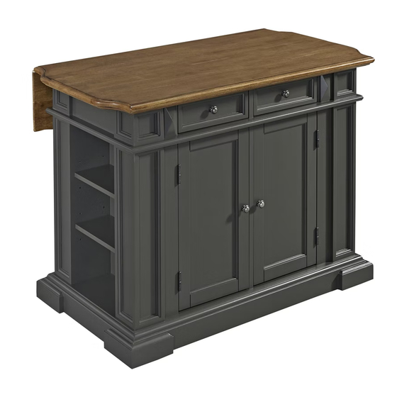
Kitchen Island
IMPORTANT NOTE
.
Carefully remove all the parts from the carton and put
them individually on a soft cloth to prevent scratches
or other damage occurring to the parts.
We have taken great care in the design of this
product and request that you carefully and strictly
follow our assembly instructions to ensure
a completed product as it was designed.
Part List
For assembly see instructions in carton 88 5013 943
Tools required for assembly : Phillips screwdriver
Home Styles Consumer Assistance : www.homestyles-furniture.com,
servicedesk@homestyles-furniture.com, 888-680-7460, 877-831-0319
A.
Top Unit
1 pc.
Advertisement
Table of Contents

Subscribe to Our Youtube Channel
Related Manuals for Home Styles 88 5013 941


Summary of Contents for Home Styles 88 5013 941
- Page 1 Part List Top Unit 1 pc. For assembly see instructions in carton 88 5013 943 Tools required for assembly : Phillips screwdriver Home Styles Consumer Assistance : www.homestyles-furniture.com, servicedesk@homestyles-furniture.com, 888-680-7460, 877-831-0319...
- Page 2 32 pcs. (+1 extra) 1 pc. 9 pcs. (+1 extra) For assembly see instructions in carton 88 5013 943 Tools required for assembly : Phillips screwdriver Tools recommended for assembly : Level Home Styles Consumer Assistance : www.homestyles-furniture.com, servicedesk@homestyles-furniture.com, 888-680-7460, 877-831-0319...
- Page 3 Side Panel Door Door 2 pcs. 1 pc. 1 pc. For assembly also need carton 88 5013 941, 942 Tools required for assembly : Phillips screwdriver Tools recommended for assembly : Level Home Styles Consumer Assistance : www.homestyles-furniture.com, servicedesk@homestyles-furniture.com, 888-680-7460, 877-831-0319...
- Page 4 Assembly Instructions 2/5 IMPORTANT * Please keep Hex Wrench in a safe place as you may need to tighten up the Head Cap Bolts in the future. * Do not tighten up all the bolts until each part is properly assembled. * Use a soft cloth between these parts and the floor.
- Page 5 Assembly Instructions 3/5 STEP 3 Head Cap Bolt Attach unit from Step 2 Middle Panel (E) to Base (H) with Head Cap Bolts. (See Figure 3) Figure 3 Head Cap Bolt STEP 4 Attach Legs (I) and (J) to Base (H) with Head Cap Bolts. Slide Side Panels (M) into position.
- Page 6 Assembly Instructions 4/5 Head Cap Bolt Knob Machine Screw Adjustable Pin STEP 5 Attach Rail (F) to unit with Head Cap Bolts. Attach Adjustable Pins into side panels and middle panel at the desired level. Slide Shelves (G) into place. Attach Knobs to Doors (P) and (Q) with Machine Screws.
- Page 7 Assembly Instructions 5/5 Figure 6 Figure 7 Machine Screw Knob Wood Screw STEP 6 Attach Top unit (A) to Leaf Top (B) with Wood Screws. (See Figure 6) Remove the Drawers in Top Unit (A), Head Cap Bolt attach Knobs with Machine Screws. (See Figure 7) Attach Top Unit (A) onto the unit with Head Cap Bolts.
Need help?
Do you have a question about the 88 5013 941 and is the answer not in the manual?
Questions and answers