Table of Contents
Advertisement
Quick Links
88 5003 991
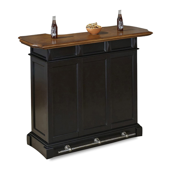
Bar
IMPORTANT NOTE
Carefully remove all the parts from the carton and put
them individually on a soft cloth to prevent scratches
or other damage occurring to the parts.
We have taken great care in the design of this
product and request that you carefully and strictly
follow our assembly instructions to ensure a
completed product as it was designed.
B.
Sub Top
1 Pc.
E.
Glass Holder
1 Pc.
For assembly see instructions in carton 88 5003 992
A.
Top
1 Pc.
H.
Front Panel
2 Pcs.
Home Styles Consumer Assistance: www.homestyles-furniture.com,
servicedesk@homestyles-furniture.com, 888-680-7460, 877-831-0319
I.
Front Panel
1 Pc.
C.
Front Panel
1 Pc.
N.
Door
1 Pc.
Advertisement
Table of Contents

Related Manuals for Home Styles 88 5003 991


Summary of Contents for Home Styles 88 5003 991
- Page 1 Sub Top Front Panel 1 Pc. 1 Pc. Front Panel Front Panel Glass Holder Door 1 Pc. 2 Pcs. 1 Pc. 1 Pc. For assembly see instructions in carton 88 5003 992 Home Styles Consumer Assistance: www.homestyles-furniture.com, servicedesk@homestyles-furniture.com, 888-680-7460, 877-831-0319...
- Page 2 1 Pc. 39 Pcs. (+2 extra) 12 Pcs. (+1 extra) 2 Pcs. 3 Pcs. (+1 extra) 2 Pcs. (+1 extra) Tools required for assembly : Phillips screwdriver Tools recommended for assembly : Level Home Styles Consumer Assistance: www.homestyles-furniture.com, servicedesk@homestyles-furniture.com, 888-680-7460, 877-831-0319...
- Page 3 Assembly Instructions IMPORTANT * Please keep Hex Wrench in a safe place as you may need to tighten up the Head Cap Bolts in the future. * Do not tighten up all the bolts until each part is properly assembled. * Use a soft cloth between these parts and the fl...
- Page 4 Assembly Instructions STEP 3 Attach Front Panels (H) to Front Panel (I) with Cam Locks. Magnet Wood Screw for Magnet STEP 4 Attach Magnet to Front Rail (G) with Wood Screws for Magnet. (See Figure 2) Attach Side Panel (J) and (K) to unit from Step 3, then attach unit to Base (M) with Cam Locks.
- Page 5 Assembly Instructions Figure 3 Flat Washer Head Cap Bolt Adjustable Pin Figure 4 STEP 5 Insert Adjustable Pins into side panels and middle panel at the desired level. Slide Shelves (O) into position. Attach top unit to body unit with Cam Locks, then attach Glass Holder (E) to unit with Head Cap Bolts and Flat Washers.
- Page 6 Assembly Instructions Same amount of Foot Rest (Q) on each side Tapered Wood Screw Head Cap Bolt (short) STEP 6 Slide Foot Rest (Q) into the Foot Rest Supports (P). Attach Foot Rest Supports (P) to unit at the pre-drilled holes with Figure 5 Tapered Wood Screws.
- Page 7 Assembly Instructions Drawer R STEP 1 Attach Side Part R3 to Front Part (R1) and Back Part (R2) using a Figure 1 Phillips screwdriver and long wood screws (4X), tighten halfway. (See Figure 1) MAKE SURE ROLLER IS ON THE BACK STEP 2 Insert Base Part (R5) into the groove.
Need help?
Do you have a question about the 88 5003 991 and is the answer not in the manual?
Questions and answers