Advertisement
Quick Installation Guide
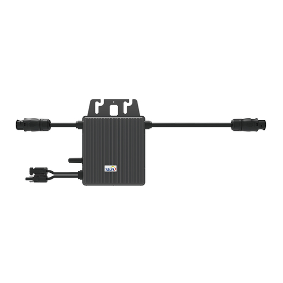
TSOL-M350/ M400 / M800 / M1600
Step 1. Make an installation map
Use the blank installation map in the package to record the location of
micro-inverters according to the system design. Each cell of the map
corresponds to one PV module.
The row of the table corresponds the
shorter side of PV module and the column
of the table corresponds the longer side of
CAUTION
PV module. The direction on the upper left
corner means the actual installation
orientation.
If there are more than one installation site,
please make the installation map
CAUTION
separately and give a clearly description
about the installation site.
There are two SN labels on the backside of micro-inverter. Pick up one
and stick the SN label to the corresponding cell of the installation map
TSOL
according to the actual installation. As
-M800 and M1600 are
connected to several PV modules, the SN label should be sticked as
shown below.
012345678912032156
012345678912032156
Figure the SN label of micro-inverter
The finished installation map is shown as below:
1
2
A
B
C
TSOL
Figure The installation map (
-M350/M400)
01
CAUTION
Step 2. Install micro-inverter
Mark the approximate center of PV module on the frame and install the
micro-inverter with the LED side facing outside.
CAUTION
Model
TSOL-M350/400
TSOL-M800/1600
WARNING
Using two pairs of screws and nuts to fix the bracket holes of the
micro-inverter onto the frame.
3
4
5
6
7
1
2
3
4
5
6
7
A
B
C
TSOL
Figure The installation map (
-M800)
1
2
3
4
5
6
A
B
C
TSOL
Figure The installation map (
-M1600)
In order to provide a better after-sale
service, please make the installation map
carefully and keep the drawing in good
condition.
The distance between every two
micro-inverters should meet the length of
AC cables. The length of AC cables are
shown as below:
Length
1.25m
2.08m
Micro-inverter should be installed in a
suitable position with good ventilation and
no directly sunshine.
Figure Installation example
02
There are no screws and nuts in the
CAUTION
package.
Step 3. Connect AC cable
Every micro-inverter could be connected to the other one by its AC
cables.
According to the max current of the AC
cables, there is a max installation quantity
CAUTION
7
for the micro-inverter in each cable
section.
Model
TSOL-M350
TSOL-M400
TSOL-M800
TSOL-1600
Plug the female AC connector of one microinverter into a male AC
connector of another micro-inverter to form a continuous AC branch
circuit.
Figure Connect the AC cables
Use Nylon cable ties to fix the AC cables onto the frame.
Figure Fix the AC cable
CAUTION
Figure TSOL-M1600 installed in one line
Quantities for each cable section
18 pcs
16 pcs
7 pcs
3 pcs
If the AC cable is too short for
installation, use an Interconnection Cable
(TSOL-MC200-G2, 2m) to connect two
TSOL-M1600 which are installed in one
line or two TSOL-M350/400 which are
installed in two different lines.
03
Advertisement
Table of Contents

Subscribe to Our Youtube Channel
Related Manuals for Tsun TSOL-M350


Summary of Contents for Tsun TSOL-M350
- Page 1 There are no screws and nuts in the CAUTION package. Quick Installation Guide Step 3. Connect AC cable TSOL-M350/ M400 / M800 / M1600 Every micro-inverter could be connected to the other one by its AC TSOL cables. Figure The installation map (...
- Page 2 CAUTION PV modules to TSOL-M1600 which are installed in one line. Reassemble the AC connector as shown below. Figure TSOL-M350/400 installed in two different lines Use a Connector Protective Cap DANGER (TSOL-MP-F/M) to make sure the unused AC connector to be closed.
Need help?
Do you have a question about the TSOL-M350 and is the answer not in the manual?
Questions and answers
problem for self test tsol m350 italiano