
Related Manuals for SMC Networks ITV SEN DUX02357 Series


Summary of Contents for SMC Networks ITV SEN DUX02357 Series
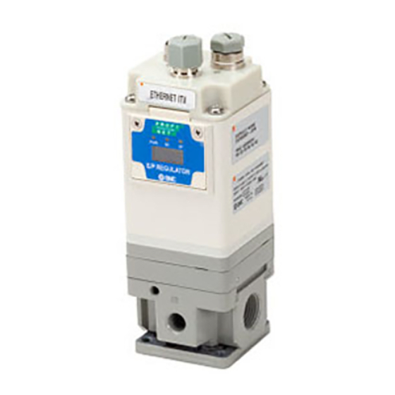
- Page 1 IN19856 PRODUCT NAME Ethernet ITV – Ethernet/IP MODEL / Series / Product Number ITVXXXX-SEN-XX-DUX02357-XXXX - 1 - Rev 2...
-
Page 2: Table Of Contents
IN19856 Table of Contents Safety Instructions ______________________________________________________________________________ - 3 - About this Manual _______________________________________________________________________________ - 9 - Terminology _____________________________________________________________________________________ - 9 - Product Summary ______________________________________________________________________________ - 10 - How to Order ____________________________________________________________________________________ - 11 - Accessories ______________________________________________________________________________________ - 12 - Summary of Product Elements _______________________________________________________________ - 13 - Quick Start _______________________________________________________________________________________ - 14 - IP Address _______________________________________________________________________________________ - 14 -... -
Page 3: Safety Instructions
IN19856 1. Safety Instructions These safety instructions are intended to prevent hazardous situations and/or equipment damage. These instructions indicate the level of potential hazard with the labels of "Caution", "Warning" or "Danger". They are all important notes for safety and must be followed in addition to International standards (ISO/IEC), and other safety regulations. - Page 4 IN19856 Warning 1. The compatibility of the product is the responsibility of the person who designs the equipment or decides its specifications. Since the product specified here is used under various operating conditions, its compatibility with specific equipment must be decided by the person who designs the equipment or decides its specifications based on necessary analysis and test results.
- Page 5 IN19856 Limited warranty and Disclaimer 1. The warranty period of the product is 1 year in service or 1.5 years after the product is delivered. Also, the product may have specified durability, running distance or replacement parts. Please consult your nearest sales branch. 2.
- Page 6 IN19856 Precautions Warning Do not disassemble, modify (including changing the printed circuit board) or repair. An injury or failure can result. Do not operate the product outside of the specifications. Do not use for flammable or harmful fluids. Fire, malfunction, or damage to the product can result. Verify the specifications before use.
- Page 7 IN19856 • NOTE o Follow the instructions given below when designing, selecting and handling the product. o The instructions on design and selection (installation, wiring, environment, adjustment, operation, maintenance, etc.) described below must also be followed. o Product specifications When conformity to UL is necessary the Serial Interface unit must be used with a ▪...
- Page 8 IN19856 • Environment o Select the proper type of protection according to the operating environment. o IP65 protection is achieved when the following conditions are met. The units are connected properly with fieldbus cable with M12 connector and power cable with M12 connector. All unused connectors are closed with a properly installed seal cap.
-
Page 9: About This Manual
IN19856 Stop operation if the equipment does not function properly. ▪ Otherwise safety is not assured due to an unexpected malfunction or incorrect ▪ operation. o Do not use solvents such as benzene, thinner etc. to clean the unit. They could damage the surface of the body and erase the markings on the body. Use a ▪... -
Page 10: Product Summary
IN19856 DHCP (Dynamic Host Configuration Protocol) allows the ITV IP address to be set using an external DHCP DHCP server. DHCP may be used if desired but is not required. Relative to your ITV, a downstream device receives power and/or communication signals which Downstream originate from or are passed through your ITV. -
Page 11: How To Order
IN19856 5. How to Order Single ITV Options Assembled Manifold Mounted Options - 11 - Rev 2... -
Page 12: Accessories
IN19856 6. Accessories Connector cables (recommended – not included with ITV) ITV unit Compatible cable Description connection Part number Specifications EX9-AC010EN- PSRJ One end: molded M12 straight connector. Other end: RJ45 connector (Ethernet). EX9-AC020EN- PSRJ EX9-AC030EN- PSRJ EX9-AC050EN- PSRJ Cables Fieldbus EX9-AC100EN- interface... -
Page 13: Summary Of Product Elements
IN19856 7. Summary of Product Elements Figure 4 - ITV20XX Drawing Element Description Input Pressure Line Connection (X010, X030, X050) / Supply Port Connection Atmosphere Pressure (2090) * Output Pressure Line Connection (X010, X030, X050) / Outlet Port Connection Application Vacuum Line Connection (2090) * Exhaust Port (X010, X030, X050) / Vacuum Line Connection Exhaust / Vacuum Port (2090) *... -
Page 14: Quick Start
IN19856 *1: X is 1, 2, or 3 and designates the body type for the ITV. (See How to Order for more information) *2: See LED Indicators for the LED indication. *3: See Accessories for connecting cables and seal caps part numbers. 8. -
Page 15: Mounting And Plumbing
IN19856 9.1. Dip Switches • Dip switches set last octet of IP address - Default is 192.168.1.XXX • Left most switch is 1 and the right most is 128 • The value of the dip switches is read at power up •... -
Page 16: Power Connection
IN19856 11. Power Connection Power supply connector layout - PWR: M12 4-pin Plug A-coded connector Designation Description 24 VDC Power (Brown Wire +24 VDC + terminal) - Do Not Connect 0 VDC Common (Blue Wire –Common -terminal) - Do Not Connect Figure 6 - ITV Power Cable Pin Connections (Note: The wire colors above are for a standard SMC power cable. - Page 17 IN19856 Data Links Ethernet IP Master Device 24 VDC Figure 8 - Example (non-POE) ITV Data and Power Connections 12.1. SMC ITV POE Summary The Power Over Ethernet (POE) feature is an optional way to power ITV units eliminating the need to run a power cable to all ITVs.
- Page 18 IN19856 Figure 9 ITV in POE Mode To change the POE state of an ITV, press “Submit”, or the keyboard Enter key. The ITV will turn on POE and store this state. The ITV now has the “Bus Out” connection changed to the POE state indicated by the “Enable POE”...
-
Page 19: Hold On Connection Loss
IN19856 The diagram illustrates the Ethernet communication and 24 VDC power cable connections required to support 6 ITVs when Power Over Ethernet (POE) is in use. The ITVs in the dashed box form a single POE group. Note that POE supports a maximum of five (5) ITVs in one POE group. The following rules MUST be followed for proper operation of POE: 1) Ethernet cable from the PLC or other device (source) must be connected to the “Bus In”... -
Page 20: Setpoint And Feedback
IN19856 Enter key and the ITV will automatically reboot. Note: Pressure or vacuum control will be interrupted during the rebooting process. Other changes to network configuration may not be stored at the same time as changing to or from compatibility mode. 15. -
Page 21: Pressure In-Range Window Diagnostic
IN19856 17. Pressure In-range Window Diagnostic This diagnostic will monitor the pressure feedback and determine if it is outside of a window pressure range for a specified elapsed time. If it is, then an error flag is set called Window Error, else the Window Error flag is cleared as the pressure is within the in-range pressure window. - Page 22 IN19856 A 16-bit value must be sent to the ITV. The lower or least significant 12 bits represent the count value. Counts sent to the ITV for a desired pressure or vacuum output must be scaled to an integer value between 0 and 4095. The “Maximum Pressure Scaling Formula”...
- Page 23 IN19856 ITV#030 COUNT SCALING 6000 5000 4914 4095 4000 3276 3000 2457 2000 1638 1000 0.00 0.10 0.20 0.30 0.40 0.50 0.60 Pressure (MPa) 18.2. Counts as Feedback A 16-bit value is received from the ITV. The upper 4 bits are 0. The lower 12 bits represent the count value.
- Page 24 IN19856 18.4. Scaling the engineering units The engineering units are scaled to use integer math and as a result require a multiplier to be used when sending the pressure set point of the desired engineering unit type. The multiplier used depends on what type of ITV unit is being communicated with and what type of engineering unit is selected.
- Page 25 IN19856 ITV#010 PSI Scaling 20000 18000 17405 16000 14504 14000 12000 11603 10000 8702 8000 6000 5802 4000 2901 2000 0.000 2.901 5.802 8.702 11.603 14.504 17.405 Pressure (PSI) Figure 12 – PSI Engineering Unit Scaling Example for 0.1MPa Range ITV Example: Suppose you have a 0.9 MPa ITV unit and you want to use PSI engineering units.
-
Page 26: Sensitivity And Gain
IN19856 18.6. 120% for Full-Scale The calibrated range of the ITV is the full-scale value/marketed value. This ITV’s range can extend beyond the 100% mark all the way to 120% of full scale. Therefore, this ITV can deliver pressures well beyond the calculated 100% of full-scale mark. Please note, the accuracy is not guaranteed beyond the full-scale value. - Page 27 IN19856 19.1. User Sensitivity Sensitivity is a relative measure of response to changes in a control system. In this case it controls how sensitive the ITV will be to pressure changes. The valid range for sensitivity is 0-7, where 0 is the most sensitive and 7 is the least sensitive.
-
Page 28: Led Indicators
IN19856 20. LED Indicators LED Indicators Front Figure 13 - ITV LED Placement Front LED Indicators LED Status Description Load voltage for the ITV is not supplied. Green ON Load voltage for the ITV is supplied. Load voltage for the ITV is outside the tolerance range (24 Red ON VDC ±10%). - Page 29 IN19856 Top LED Indicators BUS IN BUS OUT LED Status Description Load voltage not supplied, terminal is not Bus In / Bus Out connected to another operating device, or terminal failed Bus In / Bus Out Green ON Terminal is connected to another operating device Yellow Intermittently blink yellow - data transfer in Bus In / Bus Out...
-
Page 30: Built In Web Server
IN19856 21. Built in Web Server The built-in webserver can provide useful information about the ITV along with allowing for simple configuration of the ITV’s features. The webpage is also a great debugging tool for checking the status of the ITV along with being able to command the ITV directly. The webpages are password protected to prevent accidentally changing the settings. - Page 31 IN19856 Figure 16 - ITV System Information web page The “Network” section displays the current ITV network communication settings. Some of these settings can be changed by logging into the ITV. See the instructions on the Network Page. The “Manufacturing Information” display the version of SMC firmware. Please make note of this information if contacting SMC for technical support.
- Page 32 IN19856 Device Name - This is a nice electronic way to label the ITVs location on the machine. IP Address - The default is 192.168.1.20. You can set IP Address for the ITV here. It must be unique on a network or subnet. A new IP Address will take effect immediately when you press “Submit”...
- Page 33 IN19856 Figure 18 - ITV Device Control and Status web page On this web page, the current ITV pressure or vacuum value will be displayed dynamically based on the pressure unit selected. The page also shows ITV system status and ITV supply voltage dynamically.
- Page 34 IN19856 Override PLC Control - If the checkbox is unchecked, the ITV is controlled externally (typically from a PLC). When the ITV is externally controlled, the user cannot set the ITV pressure or change the pressure units from the web page. When the Override PLC Control checkbox is changed, press “submit”...
- Page 35 IN19856 Figure 29 - ITV Login Management web page - 35 - Rev 2...
-
Page 36: Basic Plc Configuration
IN19856 22. Basic PLC Configuration Configure the PLC for use with the ITV using RSLogix 5000® or Logix Designer (version 20 or higher) When connecting the ITV, using RSLogix 5000® or Logix Designer software by Rockwell Automation®, refer to Rockwell Automation® manuals for detailed operation. 1. - Page 37 IN19856 Select the EDS file to be installed and select [Next]. Figure 21 - Select EDS File to Install Right click on the selection [Ethernet] in the [I/O Configuration] folder and select [New Module]. Figure 22 - New Module Selection - 37 - Rev 2...
- Page 38 IN19856 The [Select Module Type] screen is displayed. Select [ITVXXXX-SEN-XX-DUX02357] and select [Create]. Figure 23 - Select Module Type Screen When the [New Module] screen is displayed, input the information below. (1) Name: Enter the required unit name. (2) IP Address: The IP address setting for the unit. (3) Change Module Definition (4) Set size to “INT”...
- Page 39 IN19856 Figure 24 - New Module Screen Figure 25 – Module Definition Screen 2. Example of setting using the Generic Ethernet Module Right-click on the selection [Ethernet] in the [I/O Configuration] folder and select [New Module]. The [Select Module Type] screen is displayed. Select [Generic Ethernet Module] and select [Create] - 39 - Rev 2...
- Page 40 IN19856 Figure 26 - Select (Register) Module Type The [Module Properties] screen is displayed, to perform setup. (1) Name: Enter the required unit name. (2) Select the data format of Comm: Connection Parameters. (3) IP Address: Enter the IP address setting for the SI unit. (4) Assembly Instance: Perform setting as shown below.
-
Page 41: Explicit Messaging
IN19856 23. Explicit Messaging The Ethernet ITV has these explicit messages available. These are useful for programmatically configuring the ITV settings. These options are also useful if using LabVIEW™ software or another programming language that may not have real time implicit libraries readily available. Also, some PLCs do not have implicit messaging. -
Page 42: Explicit Message Example Using Labview™ Software
IN19856 TYPE Bits 7 - 4 0000 kg/cm 0001 0010 0011 0100 Counts 0101 Figure 31 - Config engineering unit types 23.3. Initial Configuration Parameters Item Value IP address 192.168.1.20 Subnet 255:255:255:0 DHCP Enable POE Enable Hold Byte Swap Pressure Unit Counts Engineering Unit Counts... -
Page 43: Scaling
IN19856 The LabVIEW™ software Industrial Communications library is used to set and get explicit messages to and from the ITV. 25. Scaling Here are some example graphs to help with understanding how to scale the input and output to and from the PLC. - Page 44 IN19856 ITV#030 COUNT ITV#010 COUNT SCALING SCALING 6000 5000 6000 4914 5000 4914 4095 4000 4095 4000 3276 3000 3276 3000 2457 2457 2000 2000 1638 1638 1000 1000 0.00 0.10 0.20 0.30 0.40 0.50 0.60 0.00 0.02 0.04 0.06 0.08 0.10 0.12 Pressure (MPa) Pressure (MPa) ITV#050 COUNT SCALING...
-
Page 45: Troubleshooting
IN19856 ITV2090 COUNT SCALING 6000 5000 4914 4095 4000 3276 3000 2457 2000 1638 1000 0.00 0.02 0.03 0.05 0.06 0.08 0.10 Vacuum (MPa) 26. Troubleshooting This is a brief set of troubleshooting tools for the SMC Ethernet ITV. The intent of this section is to provide steps that a user can follow to diagnose and correct common issues. - Page 46 IN19856 26.2. One LED is Red 1. Solid Red NS LED indicates a duplicate IP address has been detected. The ITV displaying the red NS LED has the same IP address as another device on the network. 2. Solid Red MS LED indicates an unrecoverable error. Power cycle the ITV. 3.
- Page 47 IN19856 Possible Cause: Connector Not Connected or Not Powered 1. If a communication cable is not connected to the connector associated with the LED, the LED will be off. If this connection is not required, putting a seal cap on the connector is recommended. 2.
- Page 48 IN19856 4. Verify that air is not being unexpectedly exhausted from the ITV exhaust port. 5. If the problem persists, contact SMC Technical Support for assistance. This is not an exhaustive troubleshooting guide. SMC Technical Support may request that you check additional things, depending on the problem experienced.
- Page 49 IN19856 26.8. Recovering the IP address of the Ethernet ITV Note: ITVs have a factory preconfigured static IP address (192.168.1.20). Use this procedure when the current IP address of an ITV is unknown. Power off the ITV Set all the dip switches down or off or 0. Power on the ITV Wait for the MS LED to start to flash green Power off the ITV...
- Page 50 IN19856 New ITVs come from the factory preconfigured with a unique MAC address which matches the MAC address printed on the label of the ITV. New ITVs have a preset static IP address of 192.168.1.20. Use this IP address initially to access the ITV web page. Both MAC addresses and IP addresses must be unique on a network.
- Page 51 IN19856 26.10. Configuring the PC As noted, the IP address is initially set statically in the factory to 192.168.1.20. This is an address on subnet 1. In order to access the ITV web page, the PC must also be configured to use subnet 1. The following steps (using Windows 7 –...
- Page 52 IN19856 Your Network and Sharing Center will depict the specific network configuration for your PC and its network(s). As a result, your view may be somewhat different from the following window. If you have questions, please review the documentation for your PC. If you have additional questions, please consult your PC or Network Administrator for information and assistance.
- Page 53 IN19856 Press the “Local Area Connection” link (in Figure 34 - Windows Network and Sharing Center) and the Local Area Connection Status window will appear. Then press the “Properties” button and the Local Area Connection Properties window will appear: Figure 35 - Windows Local Area Connection and Local Area Connection Properties Next select Internet Protocol Version 4 (TCP/IPv4) and press the Properties button.
- Page 54 IN19856 The Subnet field is circled (Figure 36 - Windows Internet Protocol - IPv4 – Properties). Verify that the PC Subnet value matches the Subnet in use on your ITV. Note: The PC and ITV must have different IP addresses. DO NOT MODIFY ANY OTHER FIELD IN THE IPv4 PROPERTIES WINDOW.
- Page 55 IN19856 26.11. Connecting to the ITV Web Page After you have confirmed that the PC and ITV are on the same Subnet, launch your preferred browser. The following examples use Google Chrome. Firefox and IE are similar. Figure 37 - Chrome Browser Homepage In order to bring up the ITV web page, type the ITV IP address on the browser URL line.
- Page 56 IN19856 If the System Information page does NOT appear please see the following subsections • ITV Does Not Power Up • One LED is Red If necessary, contact SMC Technical Support for assistance. Note: To change the ITV IP address, follow the instructions in IP Address - 56 - Rev 2...
- Page 57 IN19856 Revision History Revision Description Date Added How to order for IITV 09/02/2020 Updates for DUX 08/01/2020 Initial release for EthernetIP ITV. 10/30/2019 SMC Corporation of America 10100 SMC Boulevard Noblesville, IN 46060 Phone: 1-800-SMC-SMC1 (1-800-762-7621) URL: www.smcusa.com - 57 - Rev 2...
- Page 58 IN19856 - 58 - Rev 2...
Need help?
Do you have a question about the ITV SEN DUX02357 Series and is the answer not in the manual?
Questions and answers