
Related Manuals for SMC Networks Sentry 5000-32-IT


Summary of Contents for SMC Networks Sentry 5000-32-IT
- Page 1 Sentry IT Fire & Gas Protection Sentry 5000-32-IT Controller Instruction Manual APPLICABILITY & EFFECTIVITY Effective for all systems manufactured after May 2019. Document Revision: B2 T12021...
- Page 2 Sentry 5000-32-IT Controller ©2019 Sierra Monitor. All rights reserved. Manual Number: T12021 This manual contains intellectual property that was developed by Sierra Monitor Corporation and is protected by the copyright laws of the United States, international copyright treaties, and all other applicable national laws.
-
Page 3: Table Of Contents
Sentry 5000-32-IT Controller TABLE OF CONTENTS INTRODUCTION ..........................6 General ............................6 Controller Framework (Platform) ....................6 Configurable Hardware Modules (Stacks) ..................6 Programmable Features ......................... 7 Gas Detection System ........................7 Power Requirements ........................7 PRODUCT DESCRIPTION ......................8 Controller Platform .......................... - Page 4 Sentry 5000-32-IT Controller Functional Test ..........................38 5.6.1 GUI Display Options ......................38 Sentry InSite™ ........................38 5.6.2 Controller Testing and Commissioning..................39 COMMANDER LOGIC ......................... 40 Overview ............................40 Process Blocks ..........................40 Managing Commander Logic Files ....................40 SENTRY INSITE ...........................
- Page 5 Sentry 5000-32-IT Controller LIST OF FIGURES Figure 1: Controller/Platform External View ....................8 Figure 2: Controller/Platform Internal View ....................9 Figure 3: Carrier Board ..........................10 Figure 4: Modbus Interface Board ......................11 Figure 5: Analog Input Interface Board ....................... 12 Figure 6: PSG Sentry Bus Interface Board ....................
-
Page 6: Introduction
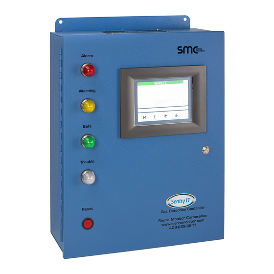
INTRODUCTION General The Sentry 5000-32-IT Controller (“Controller”) is the primary component of a gas detection system. The Controller design combines a framework of essential components with an assortment of configurable hardware modules selected during the system design phase to meet the specific application requirements. -
Page 7: Programmable Features
Sentry 5000-32-IT Controller Programmable Features Controllers are supplied with the following programmable features: • Auto Discovery of connected sensor modules • User configurable module tags, alarm levels and calibration settings • Commander Logic used to enable control algorithms combining input values and states and managing relay output states •... -
Page 8: Product Description
Sentry 5000-32-IT Controller PRODUCT DESCRIPTION Controller Platform This section describes the Platform for a painted steel wall mount enclosure. Optional Platform designs, such as rack mount versions contain the same components, but the components may be located in different positions. -
Page 9: Internal Components
Sentry 5000-32-IT Controller 2.1.2 Internal Components Figure 2 shows the internal components of the Controller Platform. Figure 2: Controller/Platform Internal View The Controller Platform components include: (1) Internal view of TPC display (2) Internal view of door lock (3) Cover panel containing single board computer (SBC) with communication port adapter board... -
Page 10: Carrier Board
Sentry 5000-32-IT Controller 2.2.1 Carrier Board 3) is assembled in a DIN carrier that snaps into the DIN rail in the Platform. The Carrier Board (Figure Figure 3: Carrier Board The function of the Carrier is to provide communications connections between all Stacks and the SBC. In... -
Page 11: Interface Boards
Sentry 5000-32-IT Controller Interface Boards An Interface Board plugs into the Carrier Board to complete a Stack. The type of Interface Board is determined during the Controller configuration process and includes: • Modbus – Section 2.3.1 • Analog Input – Section 2.3.2... -
Page 12: Analog Input
Sentry 5000-32-IT Controller 2.3.2 Analog Input 5) provides sixteen separate 4-20 mA inputs in two rows The Analog Input Interface Board (Figure identified as JP1 though JP16. The board plugs into a Carrier Board to complete an Analog Input Stack. -
Page 13: Psg
Sentry 5000-32-IT Controller 2.3.3 PSG 6) provides two loops of inputs for Sentry proprietary PSG multi-drop The PSG Interface Board (Figure communications protocol. Each of the loops identified as Loop A and Loop B supports up to eight gas detection modules. The board plugs into a Carrier Board to complete a PSG Input Stack. -
Page 14: Digital Input
Sentry 5000-32-IT Controller 2.3.4 Digital Input 7) provides connections for up to eight dry contact switch inputs. The two The Digital Input Board (Figure position connectors are identified as DI-1 through DI8. The board plugs into a Carrier Board to complete a Digital Input Stack. -
Page 15: Analog Output
Sentry 5000-32-IT Controller 2.3.5 Analog Output 8) provides connections for up to sixteen two wire 4-20 mA outputs. The Analog Output Board (Figure The two position connectors are identified as AO1 through AO16. The board plugs into a Carrier Board to complete an Analog Output Stack. -
Page 16: Digital Output
Sentry 5000-32-IT Controller 2.3.6 Digital Output 9) provides connections for eight replaceable 8 amp relays. The three The Digital Output Board (Figure position field connectors are located immediately below the socketed relay cubes. The cubes are labeled as Relay 1 through Relay 8. -
Page 17: Assembled Stack
Sentry 5000-32-IT Controller 2.3.7 Assembled Stack Figure 10 A completed stack is comprised of a Carrier Board and an Interface Board. provides an example of a stack where the Digital Output card has been installed onto the Carrier. Figure 10: Assembled Stack (Digital Output) All Stack identifiers in Commander Logic begin with the Stack address followed by the field connection number. -
Page 18: Configured System
Sentry 5000-32-IT Controller Configured System The Controller Platform and selected Stacks are assembled to complete the controller hardware. Figure 11 Although many combinations are possible describes how a set of Stacks connect and communicate with the SBC and the TPC display. As indicated in the drawing the sensor module numbering varies by communication method. -
Page 19: Controller Model Numbers
Sentry 5000-32-IT Controller Controller Model Numbers Controller model numbers are constructed as follows: 5000- XXX- SENSOR MODULE CAPACITY 8 Channel 16 Channel 32 Channel ENCLOSURE TYPE NEMA 1 Enclosure (3 stacks max) NEMA 4 SS Enclosure (3 stacks max) NEMA 4X GRP Enclosure (4 stacks max) -
Page 20: Software
Sentry 5000-32-IT Controller Software In addition to embedded operating system software the user should be aware of the following software modules. 2.6.1 Graphical User Interface (GUI) All normal operator functions are enabled through the GUI software that runs on the TPC display. All on- screen functions are driven by software in the TPC and all required data is automatically retrieved, as required, from the data base residing in the SBC. -
Page 21: Sentry Insite Appliance
Sentry 5000-32-IT Controller Sentry InSite Appliance A separate module installed inside the door of the controller, called the InSite Appliance (ProtoNode), provides the following features: • Inclusive: Sentry InSite – Basic auto-build System View dashboard webserver Gateway to Modbus TCP/IP •... -
Page 22: Changing The Subnet Of The Connected Pc
Sentry 5000-32-IT Controller 2.7.1.1 Changing the Subnet of the Connected PC The default IP Address of the ProtoNode is 192.168.1.201, subnet mask is 255.255.255.0. If the PC and the ProtoNode are on different IP Networks, assign a static IP Address to the PC on the 192.168.1.xxx network. - Page 23 Sentry 5000-32-IT Controller 5. Select Network Settings in the Configure Device window. 6. Modify the IP Address (N1 IP Address field) of the ProtoNode Ethernet port. Change additional fields as needed. NOTE: If the ProtoNode is connected to a router, the Default Gateway field of the ProtoNode should be set to the IP Address of the connected router.
-
Page 24: Saftey Notes
Sentry 5000-32-IT Controller SAFTEY NOTES Introduction Although the Controller is designed and constructed for installation and operation in industrial applications including "hostile" environments, caution should be taken to ensure that the installation is made in compliance with this instruction manual and that certain procedures and conditions are avoided. This chapter discusses the necessary cautions. -
Page 25: Sensor Modules - General
Sentry 5000-32-IT Controller Sensor Modules – General Avoid installing sensor modules where they will be unnecessarily exposed to wind, dust, water (esp. direct hose down), shock, or vibration. Observe temperature range limitations. Sensors may be adversely affected by prolonged exposure to certain materials. Loss of sensitivity, or corrosion, may be gradual if such materials are present in low concentrations. -
Page 26: Installation
Sentry 5000-32-IT Controller INSTALLATION Site Planning Prior to installation of the controller a site plan should be prepared to indicate the location of all system components including the controller, sensor modules and annunciators. The site plan must also provide cable, conduit or wire tray locations and routing. The scope of this manual covers installation and wiring of the controller. -
Page 27: Wiring
Sentry 5000-32-IT Controller Figure 14 provides the external dimensions of the controller. Figure 14: Sentry IT Controller External & Mounting Dimensions Wiring 4.4.1 Stack Connections Figure 15 Figure 21 through provide generic wiring guides for each stack type. Project specific wiring drawings are generally supplied in the project submittals or data pack. -
Page 28: Figure 15: Analog Input Wiring
Sentry 5000-32-IT Controller Figure 15: Analog Input Wiring Page 28 of 82... -
Page 29: Figure 16: Psg (Sentry Classic) Wiring
Sentry 5000-32-IT Controller Figure 16: PSG (Sentry Classic) Wiring Page 29 of 82... -
Page 30: Figure 17: Modbus Wiring
Sentry 5000-32-IT Controller Figure 17: Modbus Wiring Page 30 of 82... -
Page 31: Figure 18: Top Board Relay (Digital Output) Wiring
Sentry 5000-32-IT Controller Figure 18: Top Board Relay (Digital Output) Wiring Page 31 of 82... -
Page 32: Figure 19: Analog Output Wiring
Sentry 5000-32-IT Controller Figure 19: Analog Output Wiring Page 32 of 82... -
Page 33: Figure 20: Digital Input Wiring
Sentry 5000-32-IT Controller Figure 20: Digital Input Wiring Page 33 of 82... -
Page 34: Figure 21: Bottom Board Relay Wiring
Sentry 5000-32-IT Controller Figure 21: Bottom Board Relay Wiring Page 34 of 82... -
Page 35: Power Connections
Sentry 5000-32-IT Controller 4.4.2 Power Connections Figure 22 Figure 23 provide the locations of the terminals for connecting primary power to the controller. • Controllers that have an AC to DC power supply installed on the upper wall of the enclosure require external AC power supply. -
Page 36: Commissioning
Sentry 5000-32-IT Controller COMMISSIONING Overview Controllers purchased from Sierra Monitor as part of a fully engineered system are factory configured and tested prior to shipment. In this case Sensor discovery and Module Configuration may not be necessary. It is recommended to inspect and power up the system and move directly to the functional test phase. -
Page 37: Configure Modules
Sentry 5000-32-IT Controller Configure Modules The process to configure the discovered modules is dependent upon the method of communication between the controller and the modules. If the controller was set up in the factory discovered modules will default to factory configured parameters. -
Page 38: Configure Controller
Sentry 5000-32-IT Controller Configure Controller When all sensor modules have been discovered and configured the controller is immediately in normal run mode. To display the home page of the GUI, press the home icon or press the M key repeatedly until the home page is displayed. -
Page 39: Controller Testing And Commissioning
Sentry 5000-32-IT Controller Controller Testing and Commissioning Controller testing and commission can be initiated after the following processes are complete: • All sensor modules have been discovered and confirmed in normal operation • Display defaults and have been selected and implemented •... -
Page 40: Commander Logic
Sentry 5000-32-IT Controller COMMANDER LOGIC Overview All controller outputs are controlled by Commander Logic. A process block-based configuration file is loaded onto the controller to collect status data and use it to drive the outputs. The configuration file is generally factory installed based on user requirements provided during the order and project submittal process. -
Page 41: Sentry Insite
Sentry 5000-32-IT Controller SENTRY INSITE Overview Sentry InSite is a fully automatic screen builder that allows the user to view the status of all sensors on the system. Sentry InSite is an appliance installed on the inside of the Controller front panel. To access InSite the appliance needs to be connected to a network via an Ethernet cable. -
Page 42: Network Settings
Sentry 5000-32-IT Controller • Change user settings as needed; options include - changing login password, changing user role or deleting user profile Network Settings • To update Network Settings, click the menu button found to the upper left of the InSite Quick View Page (Section 7.4) -
Page 43: Screens
Sentry 5000-32-IT Controller Screens The Sentry InSite home screen provides a Quick View of all configured sensor modules providing their sensor number, tag, current reading and gas type. Each sensor entry is color highlighted green (safe), amber (warning), red (alarm) or blue (trouble). Current (active) Events are also listed in the left column for easy identification of “out of normal”... -
Page 44: Edit Tag Names
Sentry 5000-32-IT Controller Edit Tag Names The Sentry InSite screen initially displays default sensor tag names, identifying the Loop and Sequence Number. To customize the tag names, take the following actions: • At the Quick View screen, click any sensor line to view the Module Details page Figure 28: Sentry InSite Module Details Page •... -
Page 45: Operation - User Interface
Sentry 5000-32-IT Controller OPERATION – USER INTERFACE Front Panel Detail Figure 30 indicates the primary components of the Front Panel. See parenthesized numbering after headings for referenced part location. 8.1.1 Touch Panel (6) The integrated Touch Panel Computer (TPC) is the primary operator interface. -
Page 46: Operator Interface Screens
Sentry 5000-32-IT Controller Operator Interface Screens Figure 31 Operator interface screens utilize a common layout structure as illustrated in Figure 31: Operator Interface Screen Layout Screen Details Section Explanation Displays the system tag. User configurable. The background color represents Header Bar the system Safe or highest Alarm status. -
Page 47: Navigation
Sentry 5000-32-IT Controller Screen Colors Banner Color Representation At least one of the sensor modules has an Alarm that has not been Red blinking acknowledged Alarms have been acknowledged and at least one of the sensor modules Red solid continues to be in Alarm state... -
Page 48: Home
Sentry 5000-32-IT Controller Home Page Selection The user may select a GUI Home Page from the following choices: • Display Zones with Banner – When sensor modules have been assigned into Zone groups (Commander Logic) the Display presents the Zone Name. Any alarm within the Zone group causes a color change. -
Page 49: Mode Pages
Sentry 5000-32-IT Controller Mode Pages Figure 32 Menu pages provide the ability to navigate, access information, and change configuration. provides the top level menu structure that appears on the TPC display. Master Mode Structure M (Mode) E (Enter) Home Screen... -
Page 50: Alarm Management
Sentry 5000-32-IT Controller Alarm Management The Alarm Management page allows the user to execute the global alarm reset command. Users can also view Current Alarms, Current Warnings of Module Trouble Conditions. • From the Home page, press the Mode (M) key to sequence through the modes •... -
Page 51: View Current Alarms
Sentry 5000-32-IT Controller 8.6.2 View Current Alarms This activity in Alarm Management allows access to view or reset specific alarms. To view or reset current alarms: • Touch View Current Alarms • Touch Enter (E) key to select the option To reset the specific alarm: •... -
Page 52: View Current Warnings
Sentry 5000-32-IT Controller 8.6.3 View Current W arnings This activity in Alarm Management allows access to view or reset specific warnings. To view and manage current warnings: • Select View Current Warnings • Touch Enter (E) key to select the option To reset a specific warning: •... -
Page 53: View Module Trouble
Sentry 5000-32-IT Controller 8.6.4 View Module Trouble This activity in Alarm Management allows access to view or reset specific trouble conditions. To view and manage current troubles: • Select View Module Trouble • Touch Enter (E) key to select the option Figures below show the normal condition. -
Page 54: Figure 33: Alarm Conditions
Sentry 5000-32-IT Controller describes alarm state logic behavior on TPC display, Front Panel LED’s and Alarm Relays. Figure 33 Condition Result Configuration Status Screen Relay Alarm Flash Flash Alarm condition with Latch Reset* Solid Solid configuration Alarm Clears Alarm Flash... -
Page 55: Calibration Management
Sentry 5000-32-IT Controller Calibration Management The controller provides for gas detection system calibration to be implemented in various methods to suit the specific application. These methods include: • Remote Calibration – Allows calibration of sensor modules only (typically used for Analog Input or PSG sensors). -
Page 56: Remote Calibration
Sentry 5000-32-IT Controller 8.7.1 Remote Calibration The remote calibration function allows the user to calibrate sensors in the conventional manner where all calibration activity occurs at the sensor module. After calibration has been completed it is recommended that the Remote Calibration function be used to update the controller so that the next calibration due date will be correct. -
Page 57: Globalcal All
Sentry 5000-32-IT Controller 8.7.2 GlobalCal All In the Calibration Management menu select and Enter “GlobalCal All” and proceed as follows: Display* Description** Action All mapped modules are listed with the Press E to GlobalCal Press E. The controller will discover the gas number of days until calibration is needed. - Page 58 Sentry 5000-32-IT Controller Select Calibration All Calibrate Select Module Calibration in Progress Calibration Result Page 58 of 82...
-
Page 59: Globalcal Gas Type
Sentry 5000-32-IT Controller 8.7.3 GlobalCal Gas Type In the Calibration Management menu select and Enter “GlobalCal Gas Type” and proceed as follows: Display Description Action Touch Gas Type from All gas type groups for all mapped Press E. The controller will discover all menu modules are displayed. -
Page 60: Globalcal Select Modules
Sentry 5000-32-IT Controller 8.7.4 GlobalCal Select Modules In the Calibration Management menu select and Enter “GlobalCal Select Modules” and proceed as follows: Display Description Action All mapped modules are displayed Select specific modules by touching them on Touch Select followed by the number of days until the displayed list. -
Page 61: Globalcal Select Zone
Sentry 5000-32-IT Controller 8.7.5 GlobalCal Select Zone In the Calibration Management menu select and Enter “GlobalCal Select Zones” and proceed as follows: Display Description Action Select Zones by touching them on the All mapped modules are displayed displayed list. Press E. The controller will... -
Page 62: History Management
Sentry 5000-32-IT Controller History Management The controller records two types of data into a History Report that can be read on screen or saved to a USB memory stick file. The types of data recorded are: • Certain Controller/System messages including: System Start –... -
Page 63: System Management
Sentry 5000-32-IT Controller Report Selection History Report Display 8.10 System Management The System Management menu allows users to access Configuration or Maintenance activities. To access the System Management module: • From the Home page press Mode (M) key to sequence through the modes •... -
Page 64: Configuration
Sentry 5000-32-IT Controller 8.10.1 Configuration Configuration menu contains following sub menus: • Set Time & Date • Set Controller Id • Set Password • Set Module • Set Commander Logic • Set Display Defaults • Manage Module Map To access the Configuration menu: •... -
Page 65: Set Date & Time
Sentry 5000-32-IT Controller 8.10.1.1 Set Date & Time The date and time displayed on the lower right side of the screen to timestamps all events and activities. The time can be set manually or synchronized to system clock. To set (or change) the system date and time: •... -
Page 66: Set Controller Id
Sentry 5000-32-IT Controller 8.10.1.2 Set Controller ID The Controller ID is a user-defined string that identifies the Controller. To assign an identifier label for this Controller: • Select “Set Controller Id” • Touch the Enter (E) key to select the option •... -
Page 67: Set Password
Sentry 5000-32-IT Controller 8.10.1.3 Set Password To create or change the system password: • Select “Set Password” • Touch Enter (E) key to confirm the selection • Select the Password field to display the keyboard • Enter a Password string of up to 4 characters and press Keyboard Return key •... -
Page 68: Log Out
Sentry 5000-32-IT Controller 8.10.1.5 Log Out To secure a protected system: • Navigate to Access Management • The Detail Bar will display “Touch Logout to logout” • Touch Enter (E) key 8.10.1.6 Timeout An unsecured protected system will automatically return to secure mode after a factory preset timeout of 90 minutes. - Page 69 Sentry 5000-32-IT Controller To define the sensor module attributes: NOTE: Fields with gray area are not selectable or programmable. • Select Module type from drop down menu • Touch the Alarm Level field to display the Keyboard Type the alarm level and touch the keyboard return key •...
-
Page 70: Commander Logic
Sentry 5000-32-IT Controller 8.10.1.8 Commander Logic Sentry IT provides USB upload and download functions to enable changes to Commander Logic. A USB memory stick must be inserted into the USB socket on the back of the TPC display and a folder titled “Commander”... -
Page 71: Set Display Defaults
Sentry 5000-32-IT Controller 8.10.1.9 Set Display Defaults The Home Page display on the TPC can be selected from the following list: • Display Zones with Banner • Display Zones without Banner • Display Modules with Banner • Display Module without Banner •... -
Page 72: Manage Module Map
Sentry 5000-32-IT Controller On all Display Views the color bars on the top line of the display and the annunciator lights act in a common manner as described below: • Flashing Red ....Unacknowledged alarm • Solid Red ....... Acknowledged alarm •... - Page 73 Sentry 5000-32-IT Controller 8.10.1.10.2 Delete Trouble Modules Identified troubled modules can be removed from the Map list. • Select Delete Troubled Module • Press the E key to display a screen listing of any Trouble modules on the system •...
- Page 74 Sentry 5000-32-IT Controller System Restart 8.10.1.10.4 Clear Selected Modules An alternative to the Clear Module Map is to use Clear Selected Modules. • Select Clear Selected Modules • Touch Enter (E) key to select the function • Select Desire Modules to be removed •...
- Page 75 Sentry 5000-32-IT Controller 8.10.1.10.5 Ignore Active Modules The Ignore Active Module function allows the user to select modules to be ignored in alarm processing. The ignored modules remain on the module map and continue to operate but their concentration and alarm values are ignored by the controller logic process.
- Page 76 Sentry 5000-32-IT Controller 8.10.1.10.6 Restore Ignored Modules Restore Ignore Module function restores previously ignored module (s) to active mode. List of previously ignored module(s) is provided for restore operation. • Select Restore Ignore Modules • Touch Enter (E) key to display the ignore modules list •...
-
Page 77: Maintenance
Sentry 5000-32-IT Controller 8.10.2 Maintenance System Maintenance provides access to the following functions: System Maintenance Manual Control Force Inputs (Modbus only) Select a module address and force a gas Force Value value. The value will be forced to the Module and read by the controller for display and alarm purposes. -
Page 78: Module Summary
Sentry 5000-32-IT Controller 8.11 Module Summary The Module Summary page allows the user to select a module for the purpose of viewing module details. The information includes physical address, module number, module tag, and gas tag. • From the Home page press touch Mode (M) key to sequence through the modes •... - Page 79 Sentry 5000-32-IT Controller Module summary parameters are listed below: Model Number Model number of the selected module Module Number System Module Number Gas Concentration Current gas reading Module Type Combustible, Toxic or Oxygen module Ignore Status Ignored for alarm processing...
-
Page 80: About System
Sentry 5000-32-IT Controller 8.12 About System The About System screen provides the following information: Item Typical Value Comment Touch 2.01bB Firmware version for TPC Controller 2.00dA Firmware version for SBC Order 2015-1234 Sierra Monitor Factory Order # Stack 1 Modbus 485... -
Page 81: Specifications
Sentry 5000-32-IT Controller SPECIFICATIONS Sentry IT Controller AC Version: 120/240 VAC +/- 10%, 50/60 Hz DC Version: 24VDC Nominal (21-27 VDC) Power Power Consumption: Controller 50W, Typical max system 200W Battery Backup Capability: Seamless power transfer Operating Temperature: -14 to 131... -
Page 82: Limited 2 Year Warranty
Sentry 5000-32-IT Controller 10 LIMITED 2 YEAR WARRANTY Sierra Monitor Corporation warrants its products to be free from defects in workmanship or material under normal use and service for two years after date of shipment. Sierra Monitor Corporation will repair or replace any equipment found to be defective during the warranty period.
Need help?
Do you have a question about the Sentry 5000-32-IT and is the answer not in the manual?
Questions and answers