Table of Contents
Advertisement
Quick Links
Advertisement
Table of Contents

Related Manuals for red lion MDC


Summary of Contents for red lion MDC
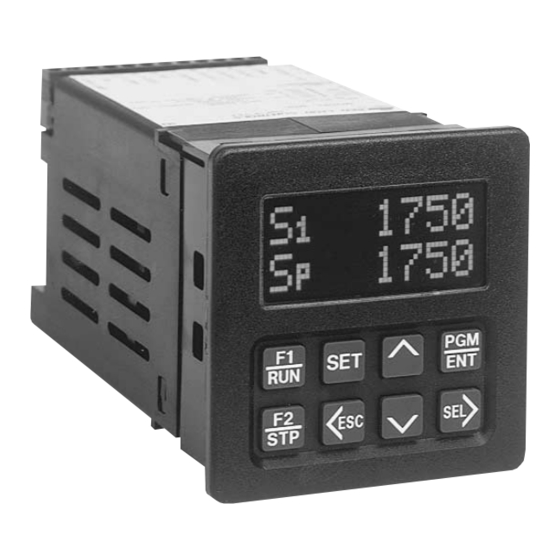
- Page 1 THE MOTOR DRIVE CONTROLLER MODEL MDC INSTRUCTION MANUAL...
- Page 2 INTRODUCTION The Motor Drive Controller (MDC) is another unit in our multi-purpose series of industrial control products that is field-programmable for solving various applications. This series of products is built around the concept that the end user has the capability to program different indication and control requirements.
-
Page 3: Table Of Contents
B) Quick Start - Setting Up The MDC ....... . . - Page 4 5. MDC User Setting Chart ........
- Page 5 TABLE OF CONTENTS (Cont’d) PROGRAMMING MODULE (Cont’d) ................. 16-30 G) Program Diagnostics Menu .
-
Page 6: General Description
MDC. Regulation is maintained by means of a feedback automatically scroll, if desired. A program disable DIP switch used with an frequency to the MDC taken from the motor shaft or a downstream shaft pulse external User Input can be utilized to protect the settings and guarantee that encoder. -
Page 7: B) Quick Start - Setting Up The Mdc
Connections” section for more information. 13. Disconnecting F-Stop momentarily from common will cause the MDC to 3. Set the AC power selection switch and connect AC to the MDC as noted in take the Drive Output voltage immediately to zero volts. This will cause “AC Power Wiring”... -
Page 8: C) Block Diagram
BLOCK DIAGRAM... -
Page 9: D) Theory Of Operation
In Master Mode, the MDC uses actual motor speed (Feedback Input) and an analog control voltage (Drive Output) to precisely control the motor’s speed. The MDC operates on a 10 msec control cycle. Actual motor speed is read and drive output is corrected every 10 msec. The Drive Output voltage is generated by a 12 bit DAC (digital to analog converter). -
Page 10: E) Normal Operating Mode
NORMAL OPERATING MODE When the MDC is powered up, it is in the Normal Operating Mode with the Indication Display Module viewed. The up and down arrow keys are used to scroll through the Indication Displays. The Indication Displays are referenced as 1 to 4 with the factory default settings of 1 (SPEED), 2 (OPERATING STATUS), 3 (ALARM STATUS), and 4 (TRIM). -
Page 11: F) Keypad Description
It is also used to exit the Programming Module and Setpoints Module. When exiting either Module, the MDC stores all parameters into nonvolatile memory and returns to the last viewed Indication Display. Setpoint 1 and 2 are stored in nonvolatile memory at power down. -
Page 12: G) Dedicated Control Inputs
INACTIVE or Not Complete programming enabled. Programmed for from the JOG input to common causes the MDC to accelerate the motor to the PGM.DIS jog speed setpoint using the jog ramp rate. The motor remains at the jog speed ACTIVE... -
Page 13: I) Overflow
“FB FREQ OVERFLOW”, or “LD FREQ OVERFLOW” when the respective input frequency exceeds specifications. A second type of overflow is an Indication Display overflow. The MDC flashes the word “OVERFLOW” in the appropriate display when the overflow condition occurs. A display overflow occurs if the capacity of the display is exceeded. -
Page 14: Programming General Description
The unit returns to the Indication Display that was last viewed. Shown at right is the Indication Display Module and the Main Programming Menus of the MDC unit. Note: In all of the flowcharts that follow, slanted characters indicate a flashing value in the unit’s display. -
Page 15: User Setpoints Module
USER SETPOINTS MODULE The User Setpoints Module is accessed from any of the Indication Displays, or from any of the main menus in the Programming Module (except Operating Mode Menu), by pressing the SET key. Pressing “SET” once enters the Setpoint Scroll Menu. -
Page 16: A) User Setpoints In Master Mode
USER SETPOINTS IN MASTER MODE Jog Speed (JOG SPD) Speed Setpoint 1 (S The Jog Speed setpoint is used in JOG mode (See JOG under Dedicated Control Input Functions for details). The value entered is in display units with Speed Setpoint 1 is one of two user selectable speeds used in “RUN” mode. the same range and limitations as Speed Setpoint 1. -
Page 17: Error Gain Setpoint
USER SETPOINTS IN FOLLOWER MODE Ramp Rate 2 (RAMP 2) The setpoints listed below are independent FOLLOWER mode setpoints. Ramp Rate 2 is the second user selectable ramp rate. A User Input must be They are retained separately from the MASTER mode setpoints in configured to allow selection of RAMP 1 or 2 for use as the current ramp rate. -
Page 18: A) Operating Mode Selection Menu
FOLLOWER mode may be selected by pressing SEL, DN arrow, and ENT. It Programming Module. Depending upon the program disable state, access to is important to select the operational mode prior to scaling the MDC and the Programming Module may be denied or require a security code entry. (See entering User Setpoints. -
Page 19: B) Program Scaling Menu
PPR FB (Pulses Per Revolution- Feedback) Enter the number of pulses per revolution generated by the feedback The Program Scaling Menu is used to scale the MDC to the specific motor transducer. The value for PPR FB ranges from 1 to 59999. -
Page 20: Pulses Per Revolution- Lead
PROGRAM SCALING MENU (Cont’d) For example, in a Master/Follower application where two motors are driving conveyors which are feeding product into a hopper, conveyor A must run 2X ADDITIONAL SCALE FACTORS IN FOLLOWER MODE faster than conveyor B to get a product mix of 1:1. The maximum speed for both PPR LD (Pulses Per Revolution- Lead) motors is 1750 RPM. -
Page 21: C) Program User Menu
PROGRAM USER MENU There are four external User Inputs and two front panel Function keys, which have a variety programmable capabilities. An external User Input is active when tied to common. A front panel function key is active when pressed. The options for each User input are the same, except as noted below: 1. -
Page 22: No Mode
Module or Programming Module, the unit advances to the selected display If the User Input is made active, the MDC ramps to S2 at the current ramp rate. upon exiting that Module. DS1 selects display 1, DS2 display 2, DS3 display Making the input inactive causes the unit to ramp to S1. -
Page 23: Setpoint Increment
The jog function only operates from the STOP mode. Pressing and holding a function key selected for JOG causes the MDC to accelerate the motor to the jog speed setpoint using the jog ramp rate. The motor remains at the jog speed until the function key is released, at which point the MDC executes an F-STOP. -
Page 24: D) Program Alarms Menu
PROGRAM ALARMS MENU Alarm parameters 1 and 2 activate solid state Alarm Outputs 1 and 2 respectively. A manual reset, which requires the use of a User Input, will reset an Alarm Output (see Program User Menu). Both alarms may be programmed for any of the five alarm functions: High Alarm, Low Alarm, Deviation Alarm, Zero Speed Alarm, and Disabled. -
Page 25: Phase (+ Or -)
When the output is reset it is turned off. refers to the alarm function when the MDC is in STOP mode or ramping to or The negative (-) phase of an output indicates that when the alarm becomes from STOP mode. -
Page 26: E) Program Displays Menu
PROGRAM DISPLAYS MENU Status displays: Each line of each Indication Display can be programmed individually to show mnemonics or a numeric value for: Speed/Ratio Setpoint 1 or 2, Speed, Operating Status (setpoint 1, ramp rate 1, Run mode) Ratio, % Deviation, % Output, Feedback Frequency, Lead Frequency, Alarm 1 or 2 setpoint and Trim. - Page 27 -25-...
-
Page 28: F) Program Options Menu
FEEDBACK LOSS DETECTION (NO FBACK DET) Used to prevent the MDC from ramping a motor to full speed if the feedback signal is lost during operation or not present when RUN mode is invoked. -
Page 29: User Settings
Master or Follower mode to the factory settings. If the key. The following are the settings when shipped from the factory, along with MDC is in Master Mode when the word “FACTORY” is flashing in the a chart for user settings:... -
Page 30: Mdc User Setting Chart
FACTORY SETTINGS COMMON TO MASTER AND FOLLOWER MODES: USER SETTINGS USER SETPOINTS: USER INPUTS: MASTER MODE: FOLLOWER MODE: USER SETPOINTS: USER SETPOINTS: JOG SPD User Input 1 JOG RAMP User Input 2 AL-1 User Input 3 AL-2 User Input 4 GAIN User Key F1 User Key F2... -
Page 31: G) Program Diagnostics Menu
TEST INPUTS The MDC displays an alphanumeric character to indicate a Dedicated This Menu allows testing of the various MDC inputs and outputs. It is Function Input or a User Input is active. This allows the user to check switch especially useful after unit installation to independently test the operation of operation and wiring connections to the Inputs. -
Page 32: Test Alarms
PROGRAM DIAGNOSTICS MENU (Cont’d) PROGRAM SECURITY MENU TEST ALARMS This is used to select the PRO.CODE used for Program Mode access when The up and down arrow keys are used to select an alarm output and set it to either the PGM.DIS. DIP switch is on or a User Input programmed for the the active or inactive state. -
Page 33: Installation & Connections
NOT exceed the maximum operating temperature and provides good air circulation. Placing the unit near devices that generate Before installing the MDC into the panel, the user should first become excessive heat should be avoided. familiar with the unit. Also, it may be desirable to program the unit and set the The bezel should be cleaned only with a soft cloth and neutral soap appropriate DIP switches for the application. -
Page 34: A) Installation Environment
EMC INSTALLATION GUIDELINES point of the enclosure. The following EMI suppression devices (or equivalent) are recommended: Although this unit is designed with a high degree of immunity to Ferrite Suppression Cores for signal and control cables: ElectroMagnetic Interference (EMI), proper installation and wiring methods Fair-Rite#0443167251 (RLC#FCOR0000) must be followed to ensure compatibility in each application. -
Page 35: B) Terminal Connection Drawing
The DC Output power connections are bottom terminals TBA 3 & 4 marked +12 VDC and common. This source is capable of supplying 12 VDC ±25% at 100 mA to power input sensors or other external devices. These terminals CANNOT be used to supply DC power to the MDC. -33-... -
Page 36: D) Signal Wiring
SIGNAL WIRING LEAD AND FEEDBACK FREQUENCY INPUTS The Lead and Feedback Inputs have identical input circuitry. The Lead and Feedback inputs each have separate DIP switches for setting the type of signal input. A Magnetic Pickup or Logic Input signal can be sent to either input. When a MAGNETIC PICKUP is used, the Sink/Source DIP switch, for the appropriate input, must be in the “SRC”... -
Page 37: Dedicated Function And User Inputs
Note: This does not guarantee that the drive is disabled unless the Drive only when the MDC is in STOP mode. This output may be used to control a Enable Output is used with an external relay to disconnect AC drive power. -
Page 38: Isolated Drive Output
Calibrating the Isolated Drive Output. If your drive does not have a process control input, the MDC may be wired to the drive in place of the drive’s external speed potentiometer. In this case, set the jumper in the EXTERNAL position. - Page 39 VARIOUS SENSOR OUTPUT CONNECTIONS (See Note 1) FREQUENCY SOURCE W/ISOLATED TRANSISTOR OUTPUTS OLDER STYLE SENSORS WITH -EF SENSORS WITH CURRENT SINK SENSORS WITH CURRENT OPEN COLLECTOR (NPN O.C.) SOURCE OUTPUT (PNP O.C.) CURRENT SOURCE CONNECTED CURRENT SINK CONNECTED OUTPUT-CURRENT SRC CONN. RLC SENSOR MODELS: PR &...
- Page 40 NOTES: 1. SENSOR VOLTAGE AND CURRENT The +12 VDC (out) terminal can supply voltage to a sensor within a ±25% variation, due to line and internal load variations. All RLC sensors will accommodate this variation. 2. When shielded cable is used, the shield should be connected to “COMM.” at the unit and left disconnected at the sensor end.
-
Page 41: Isolated Drive Output Calibration
Connections, power up the MDC and enter the Programming Module. calibrated 0 to 10 V span. If this is the case, skip Drive Output Span 2) Set up the scaling for the MDC in the Program Scaling Menu, if you have Calibration and go to Motor Drive Setup. -
Page 42: Specifications & Dimensions
SPECIFICATIONS & DIMENSIONS 1. DISPLAY: 2x8, 0.3" (7 mm) high characters, negative image transmissive MAGNETIC PICKUP: LCD, with red LED backlighting. Sensitivity: 200 mV PEAK. 2. POWER: Switch selectable for: Hysteresis: 100 mV. 115 VAC ±10%, 50/60 Hz, 10 VA or Input impedance: 3.9 KW @ 60 Hz. - Page 43 11. CONTROL INPUTS: 14. CERTIFICATIONS AND COMPLIANCES: Internal 10 KW pull-up to +5 VDC. V = 1.0 V = 4.0 V ELECTROMAGNETIC COMPATIBILITY MAX, MIN. Response time = 10 msec nominal, 30 msec maximum. Immunity to EN 50082-2 Electrostatic discharge EN 61000-4-2 Level 2;...
- Page 44 TROUBLESHOOTING GUIDE Use the Program Diagnostics Menu in the MDC to functionally test the system hardware. Each input and output can be tested independently. The following list may also help localize the problem. For further technical assistance, contact technical support at the numbers listed on the back cover of the instruction manual.
-
Page 45: Troubleshooting
2. Internal/External jumper for Drive Output in wrong 2. Refer to Installation and Connections section of position. manual. 3. MDC Isolated Drive Output improperly calibrated. 3. See Isolated Drive Output Calibration section of manual. Verify operation using Program Diagnostics Menu TEST DRV OUT. - Page 46 UNIT RAMP RATE IS NON-LINEAR/ 1. Motor drive improperly calibrated. 1. See motor drive manufacturer’s manual. LARGE “TRIM” VALUES 2. MDC Isolated Drive Output improperly calibrated. 2. See Isolated Drive Output Calibration section of manual. UNIT DISPLAYS AN OVERFLOW MESSAGE 1.
-
Page 47: Appendix "A" Applications
A pump delivers 30.0 gallons per minute with a shaft speed of 1750 RPM. A shaft pulse encoder generates 60 pulses/revolution. Set the MDC scaling to control and display pumping speed in tenths of a gallon/minute. 1) Set the pulses per revolution feedback to 60. -
Page 48: B) Follower Mode Application
MAX RPM LD = 6000 RPM. This is the correct value, even though the Nitrogen conveyor motor would never actually run at 6000 RPM. A ratio setpoint of 1.0000 on the MDC is now equal to a 1:1 mixture of Phosphorus and Nitrogen. -
Page 49: Appendix "B" - Ordering Information
APPENDIX “B” - ORDERING INFORMATION PART NUMBER MODEL NO. DESCRIPTION 115/230 VAC Motor Drive Controller MDC00100 For information on Pricing, refer to the RLC catalog or contact your local RLC distributor. -47-... - Page 50 Company’s option. The Company disclaims all liability for any affirmation, promise or representation with respect to the products. The customer agrees to hold Red Lion Controls harmless from, defend, and indemnify RLC against damages, claims, and expenses arising out of...
- Page 51 MDC/IM - F 10/00 DRAWING NO. LP0281 Red Lion Controls AP Red Lion Controls Red Lion Controls BV 31, Kaki Bukit Road 3, 20 Willow Springs Circle Basicweg 11b #06-04/05 TechLink York PA 17402 NL - 3821 BR Amersfoort Singapore 417818...
Need help?
Do you have a question about the MDC and is the answer not in the manual?
Questions and answers