
Related Manuals for SMC Networks ISE35


Summary of Contents for SMC Networks ISE35
- Page 1 No.PS※※-OMJ0004-E PRODUCT NAME Digital Pressure Switch MODEL / Series / Product Number ISE35...
-
Page 2: Table Of Contents
Table of Contents Safety Instructions Model Identification and How to Order Summary of Product parts Mounting and Installation Wiring Pressure Setting Setting of Function Default setting Other Settings Maintenance Troubleshooting Specification Specifications Dimensions No.PS※※-OMJ0004-E... -
Page 3: Safety Instructions
Safety Instructions These safety instructions are intended to prevent hazardous situations and/or equipment damage. These instructions indicate the level of potential hazard with the labels of "Caution", "Warning" or "Danger". They are all important notes for safety and must be followed in addition to International Standards (ISO/IEC) , and other safety regulations. - Page 4 Safety Instructions Caution 1.The product is provided for use in manufacturing industries. The product herein described is basically provided for peaceful use in manufacturing industries. If considering using the product in other industries, consult SMC beforehand and exchange specifications or a contract if necessary. If anything is unclear, contact your nearest sales branch.
- Page 5 Operator This operation manual is intended for those who have knowledge of machinery using pneumatic equipment, and have sufficient knowledge of assembly, operation and maintenance of such equipment. Only those persons are allowed to perform assembly, operation and maintenance. Read and understand this operation manual carefully before assembling, operating or providing maintenance to the product.
- Page 6 Caution ■Do not touch the terminals and connectors while the power is on. Otherwise electric shock, malfunction or damage to the product can result. ■After maintenance is complete, perform appropriate functional inspections and leak tests. Stop operation if the equipment does not function properly or there is a leakage of fluid. When leakage occurs from parts other than the piping, the product might be faulty.
- Page 7 ●Product handling Installation Do no drop, hit or apply shock to the Pressure switch. Otherwise it can result in damage to the Pressure switch causing failure or malfunction. Do not pull lead wires or lift the body with lead wires. (Tensile force 50N or less) Hold the body when handing.
- Page 8 The Pressure switch is not resistive to a lightning surge defined in CE marking. Take measures to protect against a lightning surge at the load side. Prevent foreign matter such as remnant of wires from entering the Pressure switch. Take proper measures for the remnant not to enter the Pressure switch in order to prevent failure or malfunction. Follow the specified range of the fluid and ambient temperatures.
-
Page 9: Model Identification And How To Order
Model Identification and How to Order ○Made to Order AR/AW-D Series - Mounting kit is included (An adapter, O-ring, lock pin and two mounting screws are attached.) No.PS※※-OMJ0004-E... -
Page 10: Summary Of Product Parts
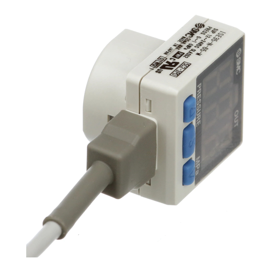
Summary of Product parts ○Names of individual parts ISE35-N- ISE35-R- Indication light (Green LED): Displays the operation condition of the Pressure switch. 3-digit LED: Displays the current status of pressure, setting mode and error code. Four display modes can be selected display always in red or green only, or switch from green to red, or red to green linking to output. -
Page 11: Mounting And Installation
Mounting and Installation ■Wiring ○Connection Connections should only be made with the power supply turned off. Use separate routes for the Pressure switch wiring and any power or high voltage wiring. Otherwise, malfunction may result due to noise. Ensure that the FG terminal is connected to ground when using a commercially available switch-mode power supply. -
Page 12: Pressure Setting
Pressure Setting Operation When the pressure exceeds the set value, the switch will be turned ON. When the pressure falls below the set value by amount of hysteresis or more, the switch will be turned OFF. As a default setting, the Pressure switch is set to turn ON when the pressure exceeds 0.35 MPa, and turn OFF when it lowers 0.34 MPa. -
Page 13: Setting Of Function
Setting of Function ■Default setting As the time of shipment, the following settings are provided. If the setting is acceptable, keep it for use. If the different setting is necessary, change the setting with reference to each page. Setting item Page Default setting Switch output... - Page 14 ■Measurement mode The mode in which the pressure is detected and displayed, and the switch function is operating. This is the basic operating mode; other modes should be selected for set-point And other function setting changes. -13- No.PS※※-OMJ0004-E...
- Page 15 1. Switch output ( The necessity of switch output can be set. If no need of switch output is selected, the switch does not generate the output and functions just like a pressure gauge. In this case, only indication color changes correspondingly to the pressure setting change.
- Page 16 3. Response time ( The response time of the switch output can be set optionally. If the response time is changed, the indication updating interval correspondingly changes. If the changed response time causes the chattering in the switch output or indication, set the response time longer.
- Page 17 Pressure setting (in window comparator mode) <How to perform> 1. Press the button in the measurement mode to display set value. 2. Press the button to change the set value. button is for increase and the button is for decrease. Press the button once to increase by one figure and press it continuously to keep set figure increased.
- Page 18 5. Hysteresis ( The hysteresis can be set. <How to perform> 1. Keep pressing the button for 2 seconds or longer in the measurement mode. After [ ] is indicated, press the button four times. Then, [ ] and current setting appears in turn. 2.
- Page 19 7. Power saving mode ( When the power saving mode is selected, the value goes off to reduce current consumption. <How to perform> 1. Keep pressing the button for 2 seconds or longer in the measurement mode. After [ ] is indicated, press the button six times.
- Page 20 ●List of output mode If the point where the switch output is changed comes outside of set pressure range due to the change of set pressure, hysteresis(H) is automatically compensated. -19- No.PS※※-OMJ0004-E...
- Page 21 ●Indication mode ( The display can be reversed. This setting is necessary to change the indication mode on receipt of the Pressure switch. <How to perform> 1. Keep pressing the button for 2 seconds or longer in the measurement mode. After [ ] is indicated, press button eight times.
- Page 22 ●Indication unit ( ) (available with unit conversion function) The indication unit can be selected freely. Setting and display resolution 0.01 Kgf/cm <How to perform> 1. Press the button three times in the measurement mode. ] and current setting appears in turn. 2.
-
Page 23: Other Settings
Other Settings ○Peak/Bottom hold value indication The maximum (minimum) pressure from when the power is supplied to this moment is detected and updated. In the peak/bottom indication mode, the pressure is indicated. As the peak indication, when the button is pressed for 1 second or longer, the maximum pressure starts flashing and is held. - Page 24 <How to perform -with secret code input-> ● Locking 1. Keep pressing the button for 5 seconds or longer in the measurement mode. ] is indicated. 2. Press the button to select locking of the key [ 3. Press the button to enter the setting.
- Page 25 ●How to change the secret code At the time of shipment, the secret code is set to [000], but can be changed to optional one. <How to perform> 1. After the lock setting is finished (page 23), perform all three steps in the unlock setting procedure. (page 23, "3") 2.
-
Page 26: Maintenance
Maintenance How to reset the product for power cut or forcible de-energizing The setting of the product will be retained as it was before a power cut or de-energizing. The output condition is also basically recovered to that before a power cut or de-energizing, but may change depending on the operating environment. -
Page 27: Troubleshooting
Troubleshooting Applicable Pressure switch: ISE35 If a cause applicable to the failure cannot be identified and normal operation can be recovered by replacement with a new Pressure switch, this indicates that the Pressure switch itself was broken. The Pressure switch breakage can be caused by operating environment (network construction, etc.), and so consult with SMC separately to obtain countermeasures. - Page 28 Refer to reference The display is abnormal The display fluctuates No. 7 Refer to reference The display disappears No. 8 Refer to reference The display breaks off No. 8 Refer to reference The display flashes No. 9 Refer to reference The display is reversed No.
- Page 29 ○Cross-reference for troubleshooting Reference Problem Possible cause Investigation method Countermeasure 1. Check the set pressure. 2. Check the setting of the operation The output Wrong mode, hysteresis and output style. 1. Set the pressure. remains on. pressure (Hysteresis mode/Window 2. Set the function. The indicator setting comparator mode, Normally open...
- Page 30 Reference Problem Possible cause Investigation method Countermeasure 1. Check if a current of 80 mA or more 1. 2. Connect the load as is flowing to the output. specified. 2. Check whether the connected load 3. Change to a relay with a is as specified, and confirm that Over current to surge voltage suppressor or...
- Page 31 Reference Problem Possible cause Investigation method Countermeasure Improper Confirm that the power supply voltage Supply a power supply voltage power supply is in the range of 12 to 24 VDC10%. of 12 to 24 VDC10%. Power saving Check if the power saving mode is Set functions.
- Page 32 Reference Problem Possible cause Investigation method Countermeasure "M" in the part number means An unsuitable that the unit cannot be model changed. selection : The new Measurement Law Check for an "M" suffix on the part The unit (Selection of number on the name plate prohibits the use of Pressure cannot be...
- Page 33 ○Error indication function This function is to display error location and content when a problem or an error occurs. Error Name Error Display Error Type Troubleshooting Method Turn the power off and remove the Over current A load current of switch output is 80 mA output factor for the over current.
-
Page 34: Specification
Specification ■Specifications Model No. ISE35 Rated pressure range 0 to 1 MPa Set pressure range -0.1 to 1 MPa Proof pressure 1.5 MPa Setting and display resolution 0.01 MPa Applicable fluids Air, inert gases, and incombustible gases Power supply voltage 12 to 24 VDC ±10% with voltage ripple or less... -
Page 35: Dimensions
■Dimensions -34- No.PS※※-OMJ0004-E... - Page 36 Revision history A: Contents are added. B: Measurement laws are added. C: Modified errors in text. D: Contents revised in several places. [July 2018] E: Contents are added. [October 2019] 4-14-1, Sotokanda, Chiyoda-ku, Tokyo 101-0021 JAPAN Tel: + 81 3 5207 8249 Fax: +81 3 5298 5362 https://www.smcworld.com Note: Specifications are subject to change without prior notice and any obligation on the part of the manufacturer.
Need help?
Do you have a question about the ISE35 and is the answer not in the manual?
Questions and answers