SMC Networks ZSE3 Instruction Manual
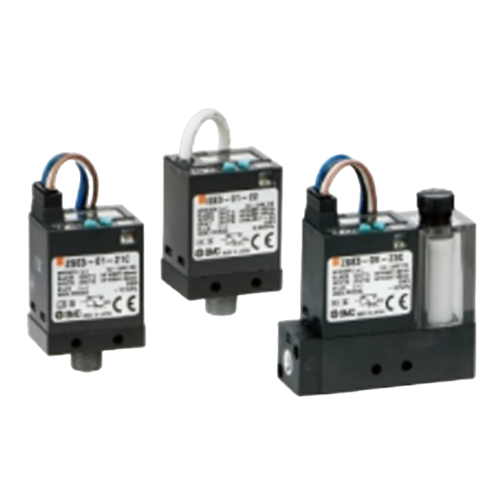
Compact pressure switch
Hide thumbs
Also See for ZSE3:
- Operation manuals (1 page) ,
- Maintenance manual (3 pages) ,
- Operation manual (33 pages)
Advertisement
Quick Links
Z_ISE3-TF2Z043EN
ORIGINAL INSTRUCTIONS
Instruction Manual
Compact Pressure Switch
ZSE3 / ISE3(L)
The intended use of the compact pressure switch is to measure, monitor
and display pressure and provide an output signal.
1 Safety Instructions
These safety instructions are intended to prevent hazardous situations
and/or equipment damage. These instructions indicate the level of
potential hazard with the labels of "Caution," "Warning" or "Danger."
They are all important notes for safety and must be followed in addition
to International Standards (ISO/IEC)
*1)
, and other safety regulations.
*1)
ISO 4414: Pneumatic fluid power - General rules relating to systems.
ISO 4413: Hydraulic fluid power - General rules relating to systems.
IEC 60204-1: Safety of machinery - Electrical equipment of machines.
(Part 1: General requirements)
ISO 10218-1: Robots and robotic devices - Safety requirements for
industrial robots - Part 1: Robots.
• Refer to product catalogue, Operation Manual and Handling
Precautions for SMC Products for additional information.
• Keep this manual in a safe place for future reference.
Caution indicates a hazard with a low level of risk which, if
Caution
not avoided, could result in minor or moderate injury.
Warning indicates a hazard with a medium level of risk
Warning
which, if not avoided, could result in death or serious injury.
Danger indicates a hazard with a high level of risk which, if
Danger
not avoided, will result in death or serious injury.
Warning
• Always ensure compliance with relevant safety laws and
standards.
• All work must be carried out in a safe manner by a qualified person in
compliance with applicable national regulations.
• This product is class A equipment intended for use in an industrial
environment. There may be potential difficulties in ensuring
electromagnetic compatibility in other environments due to conducted
or radiated disturbances.
• Refer to the operation manual or catalogue on the SMC website (URL:
https://www.smcworld.com) for more safety instructions.
2 Specifications
2.1 General specifications
ZSE3
ISE3L
ISE3
Model No.
Vacuum
Low pressure
High pressure
Rated pressure
0 to -101 kPa
0 to 98 kPa
0 to 0.98 MPa
range
Min. display unit
1 kPa
0.01 MPa
Applicable fluid
Air, inert and incombustible gases
Max. operating
200 kPa
*1
1 MPa
pressure
12 to 24 VDC ±10%, ripple (P-P) 10% or less
Power supply
voltage
(Protected against inverse connection)
Current
25 mA or less
consumption
Output type
NPN open collector output
Max. load
80 mA
current
Max.
applied
30 VDC
voltage
Response
5 msec
time
Repeatability
±1% F.S.
Hysteresis
Variable (0 digits or more)
mode
*4-2
Window
comparator
Fixed (3 digits)
mode
Analogue output
Voltage output: 1 to 5 V ±5%
Output impedance: Approx. 1 kΩ
*2-3
Display method
3 1/2 digits LCD (character height 5 mm)
*3-4
Indicator light
Light when ON OUT1: Green OUT2: Red
Self-diagnosis
Detection of overcurrent, overpressure, data
function
error and pressure during zero clear
Indicator: Red flashing,
Error indication
Error code is displayed on LCD
Enclosure
IP40
Ambient
o
temperature
0 to 60
C (No condensation or freezing)
range
Withstand
1000 VAC, 50/60 Hz, 1 minute, Between the
voltage
external terminal and the case
2 MΩ (at 500 VDC) Between the external
Insulation
resistance
terminal and the case
Temperature
±3% F.S.
characteristic
R1/8: M5x0.8
NPTF1/8:
M5x0.8
R1/8: M5x0.8
Port size
With suction
NPTF1/8: M5x0.8
filter: M5x0.8
(M6x1 made
to order).
Connector
Heat-resistant vinyl electric wire, 4-wire, Cross
2
type
section: 0.31 mm
, Insulator O.D.: 1.55 mm
Oil-resistant vinyl cabtire code
-21, -23: 4 cores, ø3.5, Cross section: 0.14 mm
Grommet
Insulator O.D.: 1.0 mm
type
-22, -24: 5 cores, ø3.5, Cross section: 0.15 mm
Insulator O.D.: 1.0 mm
Weight
40 g (including 0.6 m lead wire)
*1: When vacuum is used, there is no influence on the switch even if 0.5
MPa of pressure is supplied instantaneously.
*2: Window comparator mode: Since the hysteresis is 3 digits, P1 should
be separated from P2 by 7 digits or more.
1 digit is the minimum pressure display unit.
*3: Only for the pressure switch with analogue output selected.
*4: In case of ZSE3-#-23 or 24, failure predictive output: Red.
2 Specifications (continued)
2.2 Analogue Output
Analogue
output [V]
Model No.
Rated pressure range
ZSE3
0 to -101 kPa
ISE3L
0 to 98 kPa
ISE3
0 to 0.98 MPa
3 Summary of Product parts
Part
Description
RESET button
Resets an error and for zero clear of the display.
SET button
Selects the setting mode and enters the set value.
Displays pressure value, setting mode, and error
LCD display
codes.
The green LED is ON when output OUT1 is ON.
The red LED is ON when output OUT2 is ON and
failure predictive output.
LED
When both OUT1 and OUT2 are ON, both the
green and red LED's are ON.
When an error occurs the red LED flashes.
Selects the peak display mode and increases the
UP button
ON/OFF set value.
Selects the bottom display mode and decreases
DOWN button
the ON/OFF set value.
4 Installation
4.1 Installation
Warning
2
,
Do not install the product unless the safety instructions have been read
and understood.
2
,
4.2 Environment
Warning
• Do not use in an environment where corrosive gases, chemicals, salt
water or steam are present.
• Do not use in an explosive atmosphere.
• Do not expose to direct sunlight. Use a suitable protective cover.
• Do not install in a location subject to vibration or impact. Check the
product specifications.
• Do not mount in a location exposed to radiant heat.
4 Installation (continued)
4.3 Piping
• Before connecting piping make sure to clean up chips, cutting oil, dust
etc.
• When installing piping or fittings, ensure sealant material does not
enter inside the port. When using seal tape, leave 1 thread exposed
on the end of the pipe/fitting.
• Connect the digital pressure switch to the piping with a hexagon socket
head plug and a fitting.
• The tightening torque for the piping port must be 8.8 N•m maximum.
A
B
0
-101 kPa
0
98 kPa
0
0.98 MPa
4.4 Lubrication
• SMC products have been lubricated for life at manufacture, and do not
require lubrication in service.
• If a lubricant is used in the system, use turbine oil Class 1 (no additive),
ISO VG32. Once lubricant is used in the system, lubrication must be
continued because the original lubricant applied during manufacturing
will be washed away.
5 Wiring
5.1 Wiring connections
• Connections should be made with the power supply turned OFF.
• Use a separate route for the product wiring and any power or high
voltage wiring. Otherwise, malfunction may result due to noise.
• If a commercially available switching power supply is used, be sure to
ground the frame ground (FG) terminal. If the switching power supply
is connected for use, switching noise will be superimposed and it will
not be able to meet the product specifications. In that case, insert a
noise filter such as a line noise filter/ferrite between the switching
power supplies or change the switching power supply to a series power
supply.
• Incorrect wiring will lead to digital pressure switch damage, failure or
malfunction. Be sure to confirm the wire colour and terminal number
before wiring.
5.2 Connector attaching / detaching
• When assembling the connector, push it straight onto the pins until the
lever locks into the housing.
• To remove the connector, push the lever down to unlock the hook from
the groove, and withdraw the connector straight out.
Mating connector wiring details:
2
Wire size: 0.2 to 0.33 mm
max.
Wire sheath diameter 1.7 mm max.
Strip 3.2 to 3.7 mm of lead wire and fit crimp
SMC Part No. DXT170-71-1.
Crimping tool: SMC Part No. DXT170-75-1.
Caution
Caution
Page 1 of 3
Advertisement

Related Manuals for SMC Networks ZSE3


Summary of Contents for SMC Networks ZSE3
- Page 1 • Do not install in a location subject to vibration or impact. Check the *3: Only for the pressure switch with analogue output selected. product specifications. *4: In case of ZSE3-#-23 or 24, failure predictive output: Red. • Do not mount in a location exposed to radiant heat. Page 1 of 3...
- Page 2 5.4 Internal circuit and wiring select the output OUT1(2) set value input mode. The set value of P2 is displayed. flowing. (white wire). ZSE3 / ISE3(L)-#-21 The set value of P2 is displayed. Pressure exceeding 3. OUT1(2) set value input 0.5 MPa has been Switch output, NPN open collector output, 2 outputs, Max.
- Page 3 Z_ISE3-TF2Z043EN 11 Maintenance (continued) • Replacement of filter elements If element clogging causes deterioration of the adsorption force or slows the response time, stop operation and replace the element. Filter element part no.: ZX1-FE Confirm that the filter gasket is seated in the groove before reassembling the parts.
Need help?
Do you have a question about the ZSE3 and is the answer not in the manual?
Questions and answers