SMC ZSE30A, ZSE30AF, ISE30A Series - Digital Pressure Switch Instruction Manual
- Operation manual (1 page) ,
- Manual (20 pages)
Advertisement
The intended use of this digital pressure switch is to measure, monitor and display pressure and to provide an output signal.
Safety Instructions
These safety instructions are intended to prevent hazardous situations and/or equipment damage. These instructions indicate the level of potential hazard with the labels of "Caution," "Warning" or "Danger."
They are all important notes for safety and must be followed in addition to International Standards (ISO/IEC) *1), and other safety regulations.
*1) ISO 4414: Pneumatic fluid power - General rules relating to systems.
ISO 4413: Hydraulic fluid power - General rules relating to systems.
IEC 60204-1: Safety of machinery - Electrical equipment of machines.(Part 1: General requirements)
ISO 10218-1: Robots and robotic devices - Safety requirements for industrial robots - Part 1: Robots.
- Refer to product catalogue, Operation Manual and Handling Precautions for SMC Products for additional information.
- Keep this manual in a safe place for future reference.
 | Caution indicates a hazard with a low level of risk which, if not avoided, could result in minor or moderate injury. |
 | Warning indicates a hazard with a medium level of risk which, if not avoided, could result in death or serious injury. |
 | Danger indicates a hazard with a high level of risk which, if not avoided, will result in death or serious injury. |

- Always ensure compliance with relevant safety laws and standards.
- All work must be carried out in a safe manner by a qualified person in compliance with applicable national regulations.
![shock hazard]() This product is class A equipment intended for use in an industrial environment. There may be potential difficulties in ensuring electromagnetic compatibility in other environments due to conducted or radiated disturbances.
This product is class A equipment intended for use in an industrial environment. There may be potential difficulties in ensuring electromagnetic compatibility in other environments due to conducted or radiated disturbances.
Otherwise electric shock, malfunction or product damage can result.- Refer to the operation manual on the SMC website (URL: https://www.smcworld.com) for more safety instructions.
- Special products (-X) might have specifications different from those shown in the specifications section. Contact SMC for specific drawings.
 This product is class A equipment intended for use in an industrial environment. There may be potential difficulties in ensuring electromagnetic compatibility in other environments due to conducted or radiated disturbances.
Specifications
General specifications

Piping / Weight specifications

Analogue output specifications

| Range | Rated pressure range | A | B | C |
| Vacuum | 0.0 to -101.0 kPa | - | 0 | -101 kPa |
| Compound | -100.0 kPa to 100.0 kPa | - | -100 kPa | 100 kPa |
| Positive pressure | -0.100 to 1.000 MPa | -0.1 MPa | 0 | 1 MPa |
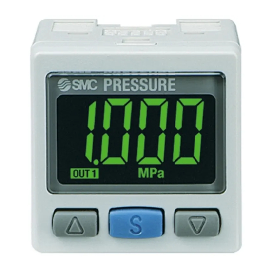
Name and function of parts

Indicator LED (Green OUT1 and Red OUT2): Displays the switch output condition.
| LCD display: | Displays the current status of pressure, setting mode, selected indication unit and error code. Four display modes can be selected: display always in red or green, or display changing from green to red, or red to green, according to the output status. |
 button: button: | Selects the mode or increases the ON/OFF set value. Press this button to change to the peak display mode. |
 button: button: | Selects the mode or decreases the ON/OFF set value. Press this button to change to the bottom display mode. |
 button: button: | Press this button to change to another mode and to set avalue. |
| Unit indication: | Displays the unit currently selected (only for kPa andMPa unit indication). |
Installation
Installation
Do not install the product unless the safety instructions have been read and understood.
Mounting with bracket
- Mount the bracket to the product with the mounting screws M3 x 5L (2 pcs.) supplied, then set the body in the required position.
∗: Tighten the bracket mounting screws to a torque of 0.5 to 0.7 N•m.
The recommended tightening torque of the piping port is 7 to 9 N•m.


Bracket A, B or C can be mounted in 4 ways.


Mounting with panel mount adapter
- Mount part (a) to the front of the body and fix it. Then insert the body with (a) into the panel until (a) comes into contact with the panel front surface. Next, mount part (b) to the body from the rear and insert it until (b) comes into contact with the panel.
- Panel mount adapter (Part No.: ZS-27-C)
Panel mount adapter + Front protective cover (Part No.: ZS-27-D)

∗: The panel mount adapter can be rotated through 90 degrees for mounting.

Removal of the Unit
The Pressure switch with panel mount adapter can be removed from the installation by removing the 2 screws and releasing the hooks at the sides, as illustrated.
Take care not to damage the Pressure switch and panel mount adapter.

Environment
- Do not use in an environment where corrosive gases, chemicals, salt water or steam are present.
- Do not use in an explosive atmosphere.
- Do not expose to direct sunlight. Use a suitable protective cover.
- Do not install in a location subject to vibration or impact. Check the product specifications.
- Do not mount in a location exposed to radiant heat.
- Do not use the Pressure switch in a place where electrical static charge will be a problem. It can cause an error and damage to the system.
Piping
- Before piping make sure to clean up chips, cutting oil, dust etc.
- When installing piping or fittings, ensure sealant material does not enter inside the port. When using seal tape, leave 1 thread exposed on the end of the pipe/fitting.
- Tighten fittings to the specified tightening torque.
- Connection using One-touch fitting
- Cut the tube end perpendicular.
- Hold the tube and insert it into the One-touch fitting slowly until it bottoms out.


- Allow sufficient tube length to prevent twist and tensile or moment loads from being applied to the fitting or tube.
- When using a tube manufactured by a company other than SMC, check that its outside diameter tolerance satisfies the following values:
- Nylon tube: ±0.1 mm maximum
- Soft nylon tube: ±0.1 mm maximum
- Polyurethane tube: +0.15 mm / -2 mm maximum
Lubrication
- SMC products have been lubricated for life at manufacture, and do not require lubrication in service.
- If a lubricant is used in the system, use turbine oil Class 1 (no additive), ISO VG32. Once lubricant is used in the system, lubrication must be continued because the original lubricant applied during manufacturing will be washed away.
Wiring
Wiring connections
- Connections should be made with the power supply turned off.
- Use a separate route for the product wiring and any power or high voltage wiring. Otherwise, malfunction may result due to noise.
- If a commercially available switching power supply is used, be sure to ground the frame ground (FG) terminal. If the switching power supply is connected for use, switching noise will be superimposed and it will not be able to meet the product specifications. In that case, insert a noise filter such as a line noise filter/ferrite between the switching power supplies or change the switching power supply to a series power supply.
Connector Connecting / Disconnecting
- When mounting the connector, insert it straight into the socket, holding the lever and connector body, and push the connector until the lever hooks into the housing, and locks.
- When removing the connector, press down the lever to release the hook from the housing and pull the connector straight out.


Connector pin numbers
Pressure Setting
Measurement mode
The measurement mode is the condition where the pressure is detected and displayed, and the switch function is operating.
This is the basic mode, and other modes should be selected for setting changes and other function settings.

Setting the ON and OFF points of the Pressure switch.
- Operation
When the pressure exceeds the set point, the Pressure switch will be turned ON.
When the pressure falls below the set point by the amount of hysteresis or more, the Pressure switch will be turned OFF.
The default setting of the output set value is the central value between the atmospheric pressure and the upper limit of the rated pressure range.
If this condition, shown below, is acceptable, then keep these settings.


Operation
[Hysteresis mode]
- Press the
![]() button once in measurement mode.
button once in measurement mode.
![]()
- [P_1] or [n_1] and the set value are displayed in turn.

- Press the
![]() or
or ![]() button to change the set value. The
button to change the set value. The ![]() button is to increase and the button is to decrease.
button is to increase and the button is to decrease.


- Press the
![]() button once to increase by one digit, and press it continuously to keep increasing the set value.
button once to increase by one digit, and press it continuously to keep increasing the set value.

- Press the
![]() button once to decrease by one digit, and press it continuously to keep decreasing the set value.
button once to decrease by one digit, and press it continuously to keep decreasing the set value.


- Press the
![]() button to finish the setting.
button to finish the setting.
For models with 2 outputs, [P_2] or [n_2] will be displayed. Set as above.
The Pressure switch operates within a set pressure range (from P1L to P1H) during window comparator mode. Set P1L (switch lower limit) and P1H (switch upper limit) with the setting procedure above.
(When reversed output is selected, [n1L] and [n1H] are displayed.)
Zero clear of Display
The display is reset to zero when the  and
and  buttons are pressed simultaneously for 1 second. For the first operation, always perform zero clear with no pressure applied.
Function Setting
In measurement mode, press the  button for 2 seconds or longer to display [F 0]. Select to display the function to be changed, [F ## ]. Press the button for 2 seconds or longer in function selection mode to return to measurement mode.

*: Some functions are not available depending on part number. All functions are displayed with [F ##] followed by the function description. If a function is not available, the function is displayed as [---].
Default Function settings
At the time of shipment, the following settings are provided.
If this condition is acceptable, then keep these settings.
To change the settings, enter function selection mode.
- [F 0] Unit selection function.
| Unit specification | Model | Default setting |
| Nil or M | ISE30A | MPa |
| ZSE30A(F) | kPa | |
| P | ISE30A | psi |
| ZSE30A(F) |
- [F 1] Setting of OUT1
| Item | Description | Default setting |
| Output mode | Select hysteresis mode or window comparator mode. | Hysteresis mode |
| Reversed output | Select reversed output. | Normal output |
| Pressure setting | Set the ON or OFF point of the switch output | ISE30A: 0.500 MPa ZSE30A: -50.5 kPa ZSE30AF: 50.0 kPa |
| Hysteresis | Set the hysteresis to prevent chattering. | ISE30A: 0.050 MPa ZSE30A: 5.1 kPa ZSE30AF: 5.0 kPa |
| Display colour | Select the display colour. | ON: Green OFF: Red |
- [F 2] Setting of OUT2 is the same setting as [F 1] OUT1.
The display colour is linked to OUT1 and cannot be set for OUT2. - Other parameter settings
| Item | Default setting |
| [F 3] Response time | 2.5 ms |
| [F 4] Display resolution | 1000-split |
| [F 5] Auto-preset function | Manual |
| [F 6] Fine adjustment of display value | 0% |
| [F 7] Power saving mode | OFF |
| [F 8] Security code | OFF |
| [F90] Setting of all functions | OFF |
| [F97] Copy function | OFF |
| [F98] Check of output | Normal |
| [F99] Reset to the default setting | OFF |
Other Settings
- Peak/bottom value display
The maximum (minimum) pressure when the power is supplied is detected and updated. - Zero clear function
The displayed value can be adjusted to zero if the measured pressure is within ±7%F.S (±3.5% F.S. for compound pressure) of the zero point - Key-lock function
The key-lock function is used to prevent errors occurring due to unintentional changes of the set values.
For further details refer to the operation manual on the SMC website (URL: https://www.smcworld.com).
Error Indication
| Error Name | Error Display | Error Type | Troubleshooting Method |
Over current Error (Er 1, Er 2) |  | The switch output load current is more than 80 mA. | Turn the power off and remove the cause of the over current. Then turn the power on. |
Residual Pressure Error (Er 3) |  | During zero clear operation, pressure above ±7% F.S (±3.5% F.S. for compound pressure) has been applied. After 1 second, the mode will return to measurement mode. The zero clear range can vary ±1% F.S. with individual product differences. | Perform zero clear operation again after restoring the applied pressure to an atmospheric pressure condition. |
Pressurizing Error (HHH, LLL) |  | Pressure has exceeded the upper limit of the set pressure range. | Adjust the applied pressure to a level within the set pressure range. |
 | Pressure has exceeded the lower limit of the set pressure range. | ||
System Error (Er 0, Er 4, Er 6, Er 7, Er 8, Er 9) |  | Displayed in the case of an internal data error. | Turn the power off and turn it on again. If resetting fails, an investigation by SMC Corporation will be required. |
If the error cannot be reset after the above measures are taken, contact SMC.
Maintenance
General Maintenance
- Not following proper maintenance procedures could cause the product to malfunction and lead to equipment damage.
- If handled improperly, compressed air can be dangerous.
- Maintenance of pneumatic systems should be performed only by qualified personnel.
- Before performing maintenance, turn off the power supply and be sure to cut off the supply pressure. Confirm that the air is released to atmosphere.
- After installation and maintenance, apply operating pressure and power to the equipment and perform appropriate functional and leakage tests to make sure the equipment is installed correctly.
- If any electrical connections are disturbed during maintenance, ensure they are reconnected correctly and safety checks are carried out as required to ensure continued compliance with applicable national regulations.
- Do not make any modification to the product.
- Do not disassemble the product, unless required by installation or maintenance instructions.
How to reset the product after a power cut or forcible de-energizing
The setting of the product will be retained as it was before a power cut or de-energizing.
The output condition is also basically recovered to that before a power cut or de-energizing but may change depending on the operating environment.
Therefore, check the safety of the whole installation before operating the product.
If the installation is using accurate control, wait until the product has warmed up (approximately 10 to 15 minutes).
Replacement of one-touch fitting
- The one-touch fitting has a cassette mechanism to allow replacement.
- Assembly should be performed after turning the power OFF, stopping the supplied fluid, exhausting the fluid within the piping, and ensuring the release to atmosphere.
- The one-touch fitting is held by a one-touch clip inserted as shown in the figure below. Remove the one-touch clip with a flat blade screwdriver. To mount the one-touch fitting, insert it to the bottom, then insert the one-touch clip.
- Take care not to damage the O-ring of the one-touch fitting.
- Supply pressure to the fitting slowly, and check if for leaks.


Limitations of Use
Limited warranty and Disclaimer/Compliance Requirements
Refer to Handling Precautions for SMC Products.
- SMC products are not intended for use as instruments for legal metrology.
Measurement instruments that SMC manufactures or sells have not been qualified by type approval tests relevant to the metrology (measurement) laws of each country.
Therefore, SMC products cannot be used for business or certification ordained by the metrology (measurement) laws of each country.
Product Disposal
This product shall not be disposed of as municipal waste. Check your local regulations and guidelines to dispose of this product correctly, in order to reduce the impact on human health and the environment.
Contacts
Refer to www.smcworld.com or www.smc.eu for your local distributor / importer.
SMC Corporation
URL: https://www.smcworld.com (Global)
https://www.smc.eu (Europe)
SMC Corporation, 4-14-1, Sotokanda, Chiyoda-ku, Tokyo 101-0021, Japan
Specifications are subject to change without prior notice from the manufacturer.
© 2021 SMC Corporation All Rights Reserved.
Template DKP50047-F-085M

Documents / Resources
References
Download manual
Here you can download full pdf version of manual, it may contain additional safety instructions, warranty information, FCC rules, etc.
Download SMC ZSE30A, ZSE30AF, ISE30A Series - Digital Pressure Switch Instruction Manual
Advertisement


Need help?
Do you have a question about the ZSE30A Series and is the answer not in the manual?
Questions and answers