SMC Networks ZSE80(F) Operation Manual
Digital pressure switch
Hide thumbs
Also See for ZSE80(F):
- Operation manuals (59 pages) ,
- Operation manual (59 pages) ,
- User manual

Related Manuals for SMC Networks ZSE80(F)


Summary of Contents for SMC Networks ZSE80(F)
- Page 1 No. PS##-OMM0003-A PRODUCT NAME Digital Pressure Switch MODEL / Series / Product Number ZSE80(F) ISE80(H)
-
Page 2: Table Of Contents
Table of Contents Safety Instructions Model Indication and how to order Summary of Product parts Definition and terminology Mounting and Installation Installation Piping Wiring Pressure Setting Measurement mode Setting of Function Function selection mode Default setting F0 Unit conversion function F1 Setting of OUT1 F2 Setting of OUT2 F3 Setting of response time... -
Page 3: Safety Instructions
Safety Instructions These safety instructions are intended to prevent hazardous situations and/or equipment damage. These instructions indicate the level of potential hazard with the labels of "Caution", "Warning" or "Danger". They are all important notes for safety and must be followed in addition to International standards (ISO/IEC) and other safety regulations. - Page 4 Caution The product is provided for use in manufacturing industries. The product herein described is basically provided for peaceful use in manufacturing industries. If considering using the product in other industries, consult SMC beforehand and exchange specifications or a contract if necessary. If anything is unclear, contact your nearest sales branch.
- Page 5 Operator ♦This operation manual is intended for those who have knowledge of machinery using pneumatic equipment, and have sufficient knowledge of assembly, operation and maintenance of such equipment. Only those persons are allowed to perform assembly, operation and maintenance. ♦Read and understand this operation manual carefully before assembling, operating or providing maintenance to the product.
- Page 6 ■NOTE ○Follow the instructions given below when designing, selecting and handling the product. ●The instructions on design and selection (installation, wiring, environment, adjustment, operation, maintenance, etc.) described below must also be followed. ∗Product specifications •The direct current power supply to combine should be UL approved as follows. Circuit (of Class2) which is of maximum 30 Vrms (42.4 V peak) or less, with UL1310 Class2 power supply unit or UL1585 Class2 transformer.
- Page 7 ●Product handling ∗Installation •Tighten to the specified tightening torque. If the tightening torque is exceeded the mounting screws and brackets may be broken. If the tightening torque is insufficient, the product can be displaced and loosen the mounting screws. (Refer to "Mounting and Installation" on page 15.) •Do not apply excessive stress to the product when it is mounted with a panel mount.
- Page 8 ∗Environment •Do not use the product in an environment that is constantly exposed to the splash of water. Otherwise failure or malfunction can result. Take measures such as using a cover. •Do not use the product in an environment where corrosive gases or fluids could be splashed. Otherwise damage to the product and malfunction can result.
- Page 9 ∗Maintenance •Turn off the power supply, stop the supplied air, exhaust the residual pressure and verify the release of air before performing maintenance. There is a risk of unexpected malfunction. •Perform regular maintenance and inspections. There is a risk of unexpected malfunction. •Perform drainage regularly.
-
Page 10: Model Indication And How To Order
Model Indication and how to order ○Option/Part number Description Piping direction Part number ZS-24-A Rear surface piping Bracket ZS-24-D Bottom piping ZS-35-A Rear surface piping ZS-35-C Panel mount adapter Bottom piping ZS-35-B Rear surface piping ZS-35-F Panel mount adapter + Front protective cover Bottom piping ZS-35-E PS##-OMM0003-A... -
Page 11: Summary Of Product Parts
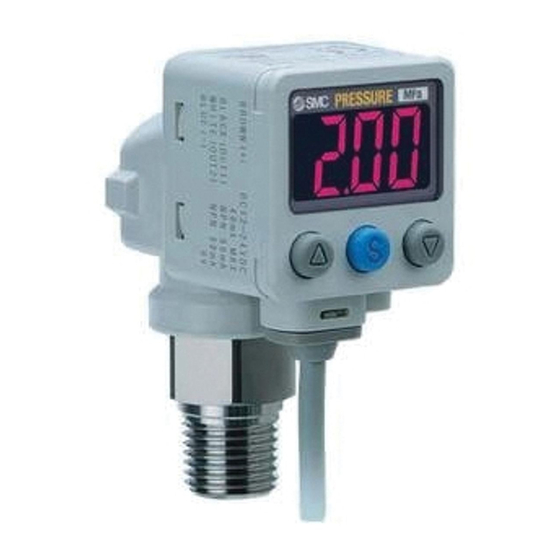
Names and Functions of Product ○Names of individual parts Indication light (Orange light): Displays switch operation condition. LCD display: Displays the current status of pressure, setting mode, selected indication unit and error code. Four display modes can be selected: display always in red or green only, or changing from green to red linked to output. -
Page 12: Definition And Terminology
■Definition and terminology Terms Meaning There are two colors to indicate a value, changing in accordance with ON and 2-color indication OFF of the switch output. When "8" is shown on the display. It is called 7-segment because 8 consists of 7 7-segment indication pieces of "- (segments)". - Page 13 Terms Meaning Hysteresis Difference between the points at which the Pressure switch is turned on and off. Hysteresis mode Refer to "List of output mode" on page 28. Indication accuracy Shows the deviation between displayed pressure value and the true pressure. The color of the digital display.
- Page 14 Terms Meaning Operating mode There are two choices, hysteresis mode and window comparator mode. Orifice A restriction. The resistance value of a component between the voltage outputting element and the output line at the output of the analog voltage output. It is indicated as a resistance value which is converted in accordance with the condition in which resistance is directly connected to the voltage output element.
- Page 15 Terms Meaning The frequency in which the detected pressure should be reflected to the digital Sampling cycle indication. Setting of function See "Function selection mode". Setting pressure range The pressure range within which switch output can be set. A stainless steel pressure-detecting part of the pressure-detecting element. It is Stainless steel diaphragm suitable for measuring fluid such as water.
-
Page 16: Mounting And Installation
Mounting and Installation ■Installation ○Mounting •Mount the optional bracket and panel mount adapter to the Pressure switch. •When the Pressure switch is to be mounted in a place where water and dust splashes occur, insert a tube (O.D φ4, I.D φ2.5) into the air-relieving port of the Pressure switch. ○Mounting by bracket •Fix the bracket to the Pressure switch with the set screws M3×5L (2 pcs.) supplied. - Page 17 ○Mounting with panel mount adapter <Rear piping> <Bottom piping> -16- PS##-OMM0003-A...
- Page 18 ○Panel cutout dimension Options •Panel mount adapter (Panel mount adapter A and B included) Model: ZS-35-B (Bottom piping) ZS-35-C (Rear piping) •Panel mount adapter + Front protective cover Model: ZS-35-E (Bottom piping) ZS-35-F (Rear piping) ∗: Panel thickness 1.0 to 5.0 mm ∗: Panel thickness 1.0 to 5.0 mm -17- PS##-OMM0003-A...
-
Page 19: Piping
■Piping ○Mounting by screw type piping •Connect suitable piping with mating port. •In order to connect the hexagon socket head plug or fitting on the pressure port, hold the hexagon part of the pressure port and fix. Apply a tightening torque of 13.6 Nm or less. ○Tube attachment •When this Pressure switch is used in a place where water and dust splash on, insert a tube in the air-relieving port, and bring piping of the opposite side up to the safe position to keep it from water and... -
Page 20: Wiring
■Wiring ○Connection •Connections should only be made with the power supply turned off. •Use separate routes for the Pressure switch wiring and any power or high voltage wiring. Otherwise, malfunction may result due to noise. •Ensure that the FG terminal is connected to ground when using a commercially available switch-mode power supply. - Page 21 -V/-T (Analog output mode) Switch output PNP open collector output type 2 output Max. 80 mA Residual voltage 1 V or less T: Analog output 1 to 5 V Output impedance 1 kΩ V: Analog output 4 to 20 mA Max.
-
Page 22: Pressure Setting
Pressure Setting ■Measurement mode The measurement mode is the condition where the pressure is detected and indicated, and the switch function is operating. This is the basic mode, and other modes should be selected for setting change and other function setting changes. - Page 23 ∗: The Pressure switch will also output during setting. <How to operate> 1, Press the button once in measurement mode. (Page 23) 2, [P_1] or [n_1] and set value are displayed in turn. 3, Press the button to change the set value. button is for increase and the button is for decrease.
-
Page 24: Setting Of Function
Setting of Function ■Function selection mode In measurement mode, press the button for 2 seconds or longer to display [F 0]. Select the display of function setting to be changed, [F Press the button for 2 seconds or longer in function selection mode to return to measurement mode. ∗: Some functions are not available depending on part number. - Page 25 •[F 2] Parameter setting of OUT2 See page 29 Same setting as [F 1] OUT1. Display color is linked to the setting of OUT1, and no parameter needs to be selected. •Other parameter setting Item Page Default setting [F 3] Setting of response time See page 29 2.5 ms [F 4] Setting of analog output/auto-shift input...
-
Page 26: F0 Unit Conversion Function
■[F 0] Unit conversion function This function is available for unit selectable type. The unit that can be displayed is different depending on the pressure range. (Refer to the table for the minimum indication unit below.) (Display in kPa and MPa is available in ZSE80(F)/ISE80 series if unit conversion function is not equipped.) <Operation>... -
Page 27: F1 Setting Of Out1
■[F 1] Setting of OUT1 Set output method of OUT1. Output turns on when the pressure exceeds the set value. The default setting of output set value is a center value of between atmospheric pressure and upper limit of the rated range. Display color depends on OUT1 output condition. - Page 28 Setting of hysteresis Press the button to select hysteresis. Press the button to set. Move on to setting of display color. Setting of display color Press the button to select display color. Press the button to set. Return to function selection mode. Setting of [F 1] operation of OUT1 completed ∗1: Selected parameter become effective after pressing the button.
- Page 29 •List of output modes If the point where the switch output is changed is out of the set pressure range due to selection between normal and reversed output, hysteresis is automatically compensated. ∗: The above figure shows the operation at OUT1. For the operation at OUT2, all "1"...
-
Page 30: F2 Setting Of Out2
■[F 2] Setting of OUT2 Set output method of OUT2. Display color depends on OUT1 output, and is not set with this function. <Operation> Press the button in function selection mode to display [F 2]. Press the button. Move on to setting output mode. Set based on [F 1] setting of OUT1 (page 26 to 28). -
Page 31: F4 Setting Of Analog Output/Auto-Shift Input
■[F 4] Setting of analog output/auto-shift input Auto-shift function This function is available when analog output/ auto-shift is equipped. Auto-shift: Function to perform output to relative change referring to the pressure when signal is input. Auto-shift zero: Function to perform output to relative change and clear the display value to zero referring to the pressure when signal is input. - Page 32 Setting of effective output Press the button to select effective output. Return to function selection Press the button to set. mode. Setting of [F 4] analog output/auto-shift input completed Conditions and explanations for auto-shift function •Keep constant pressure for 5 ms or longer from the close signal of auto-shift input. •At auto-shift input, [ooo] is displayed for approximate 1 second.
-
Page 33: F5 Setting Of Display Resolution
■[F 5] Setting of display resolution This function is to change the pressure display digit. The flickering on the display can be eliminated. <Operation> Press the button in function selection mode to display [F 5]. Press the button. Move on to setting of display resolution. Setting of display resolution Press the button to select display resolution. -
Page 34: F7 Setting Of Fine Adjustment Of Display Value
■[F 7] Setting of fine adjustment of display value This is the function to perform fine adjustment of the displayed pressure manually. It is adjustable within the range ±5%R.D. <Operation> Press the button in function selection mode to display [F 7]. Press the button. -
Page 35: F8 Setting Of Auto-Preset
■[F 8] Setting of auto-preset When hysteresis mode is selected, this function can calculate a optimum pressure value automatically based on the on-going operation. <Operation> Press the button in function selection mode to display [F 8]. Press the button. Move on to setting of auto-preset. Setting of auto-preset Press the button to select auto-preset. - Page 36 •Auto-preset When auto-preset is selected in function selection mode, the set pressure can be calculated and memorized from measured value. The set value is automatically optimized by repeated pressure changes to the Pressure switch. 1, Selection of auto-preset OUT1 Press the button in measurement mode to display "AP1".
-
Page 37: F9 Setting Of Power Saving Mode
■[F 9] Setting of power saving mode Power saving mode is selectable. When the Pressure switch is left for 30 seconds without any operation, it is shifted to power saving mode. (The decimal point and indication light (only with the switch output ON) flash during the operation.) <Operation>... -
Page 38: F10 Setting Of Security Code
■[F10] Setting of security code Security code can be entered during the key-lock is released. <Operation> Press the button in function selection mode to display [F10]. Press the button. Move on to setting of security code. Setting of security code [Pin] and set value are displayed in turn. -
Page 39: Special Function Setting
■Special function setting ■[F98] Setting of all functions All functions can be set in series. <Operation> Press the button in function selection mode to display [F98]. Press the button. Move on to setting of all functions. Setting of all functions [ALL] and set value are displayed in turn. - Page 40 •Function of setting Order Function Applicable model Selection of display unit Model with unit conversion function Setting of output mode (OUT1) All models Setting of reversed output (OUT1) All models Setting of pressure (OUT1) All models Setting of hysteresis (OUT1) All models Setting of display color All models...
-
Page 41: F99 Reset To The Default Setting
■[F99] Reset to the default setting When the setting of the Pressure switch becomes unsure, the default setting can be returned. <Operation> Press the button in function selection mode to display [F98]. Press the button. Move on to reset to the default setting. Reset to the default setting Display [ON] with pressing the button,... -
Page 42: Other Settings
Other Settings ○Peak/Bottom value indication The maximum (minimum) pressure from when the power is supplied to this moment is detected and updated. In peak/bottom indication mode, the pressure is indicated. As the peak indication, when the button is pressed for 1 second or longer, the maximum pressure and "Hi"... - Page 43 <Operation -With security code input- > •Locking 1, Keep pressing the button for 5 seconds or longer in the measurement mode. [UnL] is indicated. 2, Press the button to select locking of the key [LoC]. 3, Press the button to enter the setting. •Unlocking 1, Keep pressing the button for 5 seconds or longer in the measurement mode.
- Page 44 •How to change the security code At the time of shipment, the security code is set to [000], but can be changed to optional one. <Operation> 1, After the Key lock setting is finished (page 42), perform all three steps in the unlock setting procedure. (page 42, "3,").
-
Page 45: Maintenance
Maintenance How to reset the product for power cut or forcible de-energizing The setting of the product will remain as that before power cut or de-energizing. The output condition is also basically recovered to that before power cut or de-energizing, but may change depending on the operating environment. -
Page 46: Troubleshooting
Troubleshooting ○Troubleshooting Applicable Pressure switch: ZSE80(F)/ISE80(H) If a cause applicable to the failure cannot be identified and normal operation can be recovered by replacement with a new Pressure switch, this indicates that the Pressure switch itself was broken. The Pressure switch breakage can be caused by operating environment (network construction, etc.), and so consult with SMC separately to obtain countermeasures. - Page 47 The display The display is Refer to abnormal fluctuates reference No.8 The display Refer to disappears reference No.9 The display Refer to breaks off reference No.9 The display Refer to flashes reference No.10 Pressure indication Refer to difference when using reference No.11 two or more pressure switches...
- Page 48 ○Cross-reference for troubleshooting Reference Problem Possible cause Investigation method Countermeasure •Output remains (1) Check the set pressure. (2) Check the settings of the (1) Reset the pressure Indication light operation mode, hysteresis and Wrong pressure setting. remains on. output style. setting (2) Reset the setting of (Hysteresis mode/window...
- Page 49 Reference Problem Possible cause Investigation method Countermeasure Check if the analog output line is Incorrect wiring Correct the wiring. connected with a load. (1) Check if the proper load is connected. Non-compliance Analog output is (2) Check if input impedance of input Connect a proper load.
- Page 50 Reference Problem Possible cause Investigation method Countermeasure Check if the power supply voltage is Incorrect power Supply power supply voltage within the range of 12 to 24 VDC supply of 12 to 24 VDC ±10%. ±10%. Check the wiring to the power supply. Check if the brown and blue wires are Incorrect wiring connected to DC(+) and DC(-)
- Page 51 Reference Problem Possible cause Investigation method Countermeasure Install a 5 µm filter to prevent foreign matter from getting Check if foreign matter has entered Foreign matter into the pressure port. Also, the pressure port. clean the filter regularly to prevent drainage deposits. Rework the piping.
- Page 52 ○Error indication function This function is to display error location and content when a problem or an error occurs. Error Name Error Display Error Type Troubleshooting Method Turn the power off and remove the Over current A load current of switch output is 80 mA or output factor for the over current.
-
Page 53: Specification
Specification ■Specifications ISE80 ISE80H ZSE80 ZSE80F Model No. (positive pressure) (positive pressure) (vacuum) (compound) Rated pressure range -0.1 to 1 MPa -0.1 to 2 MPa 0 to –101 kPa -100 to 100 kPa Set pressure range -0.105 to 1.1 MPa -0.105 to 2.2 MPa 10 to –111 kPa -110 to 110 kPa Withstand pressure... -
Page 54: Analog Output
ISE80 ISE80H ZSE80 ZSE80F Model No. (positive pressure) (positive pressure) (vacuum) (compound) Enclosure IP65 Ambient temperature Operation: 0 to 50 C, Storage: -10 to 60 C (No condensation or freezing) Environment Ambient humidity Operation, Storage: 35 to 85%RH (No condensation) Withstand voltage 250 VAC for 1 minute Between wires and case Insulation resistance... -
Page 55: Dimensions
■Dimensions •Z/ISE80∗-02∗ •Z/ISE80∗-02L∗ -54- PS##-OMM0003-A... - Page 56 •Z/ISE80∗-N02∗ •Z/ISE80∗-N02L∗ • -55- PS##-OMM0003-A...
- Page 57 •Z/ISE80∗-F02∗ •Z/ISE80∗-C01∗ -56- PS##-OMM0003-A...
- Page 58 •Z/ISE80∗-C01L∗ •Z/ISE80∗-A2∗ -57- PS##-OMM0003-A...
- Page 59 •Z/ISE80∗-A2L∗ •Z/ISE80∗-B2∗ -58- PS##-OMM0003-A...
- Page 60 •Z/ISE80∗-B2L∗ -59- PS##-OMM0003-A...
- Page 61 Revision history A: Revision Note: Specifications are subject to change without prior notice and any obligation on the part of the manufacturer. © 2008-2010 SMC Corporation All Rights Reserved PS##-OMM0003-A...
Need help?
Do you have a question about the ZSE80(F) and is the answer not in the manual?
Questions and answers