Table of Contents
Advertisement
Advertisement
Table of Contents

Subscribe to Our Youtube Channel
Related Manuals for ATEQ G620


Summary of Contents for ATEQ G620
- Page 1 ATEQ G620 QuickStart Guide...
-
Page 2: Table Of Contents
Table of contents Safety advisory / Warranty Good practices and safety instructions 02/02 Air quality requirements Preamble ATEQ G620, leak tester Leak test Principe of a cycle Your ATEQ G620 Front panel Connectors on the back panel (with all options) - Page 3 ATEQ - Measurement Solution, Global Leader. 03/34 ATEQ 15, rue des Dames, Z.I. info@ateq.com T.: +33 1 30 80 1020 78340 LES CLAYES-SOUS-BOIS ateq.com F.: +33 1 30 54 1100 FRANCE ATEQ K.K. 3 – 41 ATEQ Building, Ikehata info@ateq.co.jp T.: +81 566-84-4670...
-
Page 4: Safety Advisory / Warranty
Recommendations for the test environment Keep the test area as clean as possible. Recommendations for operators ATEQ recommends that the operators who use the devices have training and a level of qualification that correspond to the job to perform. General recommendations —... -
Page 5: Air Quality Requirements
For this purpose, we strongly recommend that a suitable airtight filter is installed between the part under test and the instrument. ATEQ recommends the following characteristics for the air supplied into the device. Air characteristics ISO standard 8573 class 0.1 μm and 0.1 mg/m... -
Page 6: Preamble
Preamble ATEQ G620, LEAK TESTER ATEQ G620 is a leak tester working on continuous mode (AUTOSTART). This mode 06/34 allows the operator to localize and repair the leak. ATEQ G620 can memorize 128 different test programs. QSG_G620_423.00_EN_01_2020-02-17... -
Page 7: Leak Test
LEAK TEST Measurement principle When the part under test 6 is connected to the device 1, the internal tank 2 is pre-filled at the test pressure and then, it moves through a calibrated flow tube 3 which causes a drop 07/34 in pressure. -
Page 8: Principe Of A Cycle
PRINCIPLE OF A CYCLE The measurement cycle is made of 4 main phases: fill, stabilization, test, dumping. A Pressure auto zero additional phase "5" can be placed at the start or at the end of a cycle, depending on the requirement of the operator. 08/34 «... -
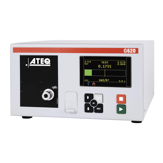
Page 9: Your Ateq G620
Your ATEQ G620 FRONT PANEL The user interface is located on the front panel. 09/34 Display Cycle keys Navigation keys USB connectors Quick fitting to connect a Master leak Regulator For more information, refer to User interface. QSG_G620_423.00_EN_01_2020-02-13... -
Page 10: Connectors On The Back Panel (With All Options)
CONNECTORS ON THE BACK PANEL (WITH ALL OPTIONS) 10/34 QSG_G620_423.00_EN_01_2020-02-17... - Page 11 Pneumatic output for A automatic connector (option) (6 mm, 600 kPa) Output to be left to the atmosphere Air supply energy information ATEQ Part number / Serial number Ground Relay board connector (digital inputs/outputs and 24 V DC - 2 A...
-
Page 12: Power Supply Connectors
POWER SUPPLY CONNECTORS The device can be connected to an external power supply (24 V DC – 2A) or provided with an internal power supply (100 / 240 V AC) (option). 12/34 External supply 24 V DC connector (J7) The device can be connected to a 24 V DC – 2A power supply through a M12 4 pins type connector. -
Page 13: Digital Links
Internal supply only 100 / 240 V AC connector (J7) (option) The device can be connected to a 100 / 240 V AC power supply (option). 13/34 This connector has an ON/OFF button. It is mandatory to connect the device to the ground with a good link to the ground, to protect against electric hazard or electrocution. - Page 14 DGND (logic ground) VP (supply) Not used Data line B Not used Devicenet connectors (J5) (J6) (option) M12 type connector - 5 pins male connector (J5) (Devicenet input) For connection to others ATEQ devices. Pin number Signal Drain CAN_H CAN_L QSG_G620_423.00_EN_01_2020-02-17...
- Page 15 M12 type connector - 5 pins female connector (J6) (Devicenet output) For connection to other ATEQ devices. Pin number Signal Drain 15/34 CAN_H CAN_L Profinet connectors (J5 + J6) (option) M12 D coded type connector - 4 pins female connector (J5 + J6)
-
Page 16: Digital Inputs/Outputs
DIGITAL INPUTS/OUTPUTS The 24V DC power supply for the digital inputs can be provided by 2 means: — The internal power supply of the device (0.3 A max) — An external power supply provided by the customer. Inputs default mode is PNP. NPN mode is available on request. 16/34 Relay board connector (J11) (option) Characteristics... - Page 17 Program selection extension connector (J10) (option) The J10 connector is an extension of the J11 connector that enables the selection of 128 programs. Characteristics 17/34 — Inputs • Activation: + 24 V DC. Inputs/outputs Pin number Description Input 8 Program selection from 33 to 64 (programmable input) Input 9 Program selection from 65 to 128 (programmable input) Program selection (J11 and J10)
- Page 18 Valve codes and auxiliary outputs board connector (J9) (option) Characteristics 18/34 — Outputs: • 24 V DC - 100 mA max per output. — Inputs: Activation: + 24 V DC. • Pin number Inputs / outputs Description + 24 V DC Common (outputs 1, 2,3) Output 1 Open collector...
-
Page 19: Pneumatic Connectors
19/34 Pneumatic supply The pneumatic supply has to meet specific requirements recommended by ATEQ. Refer to Good practices and safety instructions section. A specific filter may be necessary. The air is supplied via the filter located on the back panel of the device. - Page 20 (AVS 2.7/4 mm on the left or AVS 3/5 mm - 4/6 mm on the right). ATM connector This connector needs to be open to atmosphere. Quick fitting: 2.7/4 mm diameter. Master Flow connector Used only by ATEQ for special calibrations. AVS 2.7/4 mm diameter QSG_G620_423.00_EN_01_2020-02-17...
-
Page 21: Pneumatics Configurations
PNEUMATICS CONFIGURATION According to the part under test and the pressure range, different configurations can be used. 21/34 G620 Standard version Connection Option / description Air supply to 1 Connection of the air supply to the filter input (0.6 MPa) - Page 22 G620 Option Bypass or Shut Off 22/34 Connection Option / description Air supply to 1 Connection of the air supply to the filter input (0.6 MPa) 2 to 3 Connection of the test output to the part under test (direct mode option)
- Page 23 G620 Option Shut Off and Dump 23/34 Connection Option / description Air supply to 1 Connection of the air supply to the filter input (0.6 MPa) 2 to 3 Connection of the test output to the part under test (direct mode option)
-
Page 24: User Interface
User interface OVERVIEW The user interface comprises a display and user keys located on the front panel. 24/34 1 Display 2 Cycle keys 3 Navigation keys KEYS Cycle keys The cycle keys are used to start and to stop a measurement cycle. Name Function On the Program screen, starts a measurement cycle and opens... -
Page 25: Display
Navigation keys The navigation keys are used to select menus/options and change parameter values. Name Function Up key Scrolls up or increases numerical values. 25/34 Down key Scrolls down or decreases numerical values. Returns to the MAIN MENU screen or opens menus and options, validates parameters. - Page 26 The Measurement cycle screen The Measurement cycle screen displays the different values of the current test (or last one). Test pressure measurement Test result or step phase 26/34 Current program name Test reject value Vertical line test result Flow measurement Remaining time of the current phase or ready status Measurement unit...
-
Page 27: Starting Up
Starting up POWER UP 1. Make sure that all the necessary connections are in 27/34 place. Electrical: such as power supply, inputs/outputs Pneumatic: including line pressure supply. 2. Power up your device When power-up is completed, the Program screen is displayed, with last program used on screen PREPARING A PROGRAM Use this procedure to configure a new test program. -
Page 28: Modifying A Parameter
CONFIGURING THE ASSOCIATED MEASUREMENTS 3. Select the program to configure and press The parameters of the selected measurement type are displayed. 28/34 4. Define the measurement cycle parameters. See: Modifying a parameter. MODIFYING A PARAMETER Use this procedure to complete the test program setup. The protection of the parameters is configurable. -
Page 29: Selecting A Program
SELECTING A PROGRAM If necessary, you can select another program. 1. Press up/down 29/34 STARTING AND STOPPING CURRENT CYCLE Use the front panel keys to start/stop a measurement cycle. With the desired program displayed on the Program screen: STARTING A MEASUREMENT CYCLE 1. ... -
Page 30: User Adjustments
User adjustments OPTIONS OF THE MENUS Different menus are accessible on the MAIN MENU screen. 30/34 For more information, refer to the Reference Manual. SPECIAL CYCLE MENU menu Use this menu to carry out specific procedures necessary to ensure the proper operation of measurement cycles (for example, adjustment of pressure regulator). - Page 31 Default parameters of the FLOW type tests Label Parameter Description Required times when instrument manage COUPL. A or COUPL. B Coupling time automatic jigs FILL TIME Fill time Time to pressurise the part under test STAB TIME Stabilization time Time to stabilise the flow 31/34 The flow in the part must be between the TEST TIME...
- Page 32 Access to International System or American or UNITS Units Custom Units VALVE CODES Valve codes Available outputs for external automatism CONFIGURATION menu Use this menu to configure your ATEQ device. Label Function Description LANGUAGE Language Selection of the language displayed on the screen PNEUMATIC...
- Page 33 SERVICE menu Use this menu to do the maintenance of your device (status check, internal tests...). 33/34 Label Function Description CAN STATUS Internal network state State of the internal network of the device I/O STATE Inputs/outputs state State of the inputs/outputs VALVE COUNTER Valves wear function Approximate state of the valves wear...
-
Page 34: Specifications
Specifications CHARACTERISTICS Technical characteristics of the device. 34/34 Main characteristics: Characteristics Values Case dimensions: Height x Width x Depth 150 x 250 x 270 mm Overall dimensions 150 x 250 x 360 mm Format Half 19-inch rack Mass About 8 kg (17.6 lbs) —...
Need help?
Do you have a question about the G620 and is the answer not in the manual?
Questions and answers