
Subscribe to Our Youtube Channel
Related Manuals for Winget 200TM


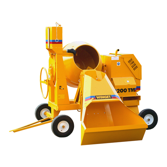
Summary of Contents for Winget 200TM
- Page 1 WORKSHOP MANUAL 200TM MIXER WINGET LIMITED PO BOX 41 EDGEFOLD INDUSTRIAL ESTATE PLODDER LANE BOLTON LANCS BL4 OLR Tel:- ++ 44 (0) 1204 854650 service@winget.co.uk parts@winget.co.uk www.winget.co.uk FROM 1998 ISSUE 8...
-
Page 2: Table Of Contents
WORKSHOP MANUAL Winget Mechanically Fed Mixers Models: 200TM From 1998 CONTENTS Section 1 Introduction Section 2 Repair and Service Procedures Section 3 General Arrangement Dimensions Section 4 Service Schedules Lubrication Diagram Section 5 Hydraulic Circuit Diagrams Section 6 Wiring Diagrams... - Page 3 WORKSHOP MANUAL 200TM SECTION 1 INTRODUCTION...
-
Page 4: Introduction
From 1998 Introduction It is assumed that Personnel involved in either the Assembly or repair of Winget Mixers will be familiar with the product, either through the operation of, or previous repair and maintenance work. It is not intended to be used by Personnel who are neither familiar with the product or mechanically inexperienced. - Page 5 WORKSHOP MANUAL Winget Mechanically Fed Mixers Models: 200TM From 1998 Clean any paint or debris from bores and shaft surfaces. Threaded holes should preferably be cleaned out using the correct tap All sealed for life bearings should be packed with a good quality grease prior to installation.
-
Page 6: Repair And Service Procedures
WORKSHOP MANUAL 200TM SECTION 2 REPAIR & SERVICE PROCEDURES... - Page 7 WORKSHOP MANUAL Winget Mechanically Fed Mixers Models: 200TM From 1998 Lifting Points Lifting points capable of supporting the weight of the mixer are incorporated in both the rear leg of the mainframe and on the upper leading edge of the hopper cradle.
- Page 8 WORKSHOP MANUAL Winget Mechanically Fed Mixers Models: 200TM From 1998 Drawbar-Standard The standard drawbar is attached to the front axle via two bolts, flat washers and binx nuts, to remove simply undo and remove the bolts and lift the drawbar clear. Reverse the procedure to refit.
- Page 9 The 200T and 200TM both utilise the same drum cone, however because the TS/TR1 diesel version of the 200TM rotates in the opposite direction to the 200T and electric driven 200TM different drum blades are used. The standard cone must therefore be modified prior to use as follows.
- Page 10 200TM DRUM CLIP FIXING...
- Page 11 WORKSHOP MANUAL Winget Mechanically Fed Mixers Models: 200TM From 1998 piece over the remaining gap in the drum clip and weld in place. Remove the tool. Fully tighten the drum blades. Run the mixer, tilting the drum via the tiltwheel making sure that the drum, clip or bridge piece do not foul the mainframe or guards.
- Page 13 WORKSHOP MANUAL Winget Mechanically Fed Mixers Models: 200TM From 1998 Refer to the Drum Adjustment illustration and check the number of flat washers required to fill the gap (G) between the flange and base block. Remove one washer from each side. Apply anti-seize compound to the setscrews (H) and pass the setscrews through the flange and flat washers, fully tighten the setscrews into the trunnion.
- Page 14 WORKSHOP MANUAL Winget Mechanically Fed Mixers Models: 200TM From 1998 Turn the handwheel and check the drum and trunnion operate correctly and contact the travel stops without unduly stressing the tilting chain. Tilting Chain To access the tilting chain remove the upper and lower chain guards behind the front plate of the trunnion.
- Page 15 WORKSHOP MANUAL Winget Mechanically Fed Mixers Models: 200TM From 1998 Clamp the housing in a soft jawed vice and remove the gib head key retaining the bevel pinion and pull off the bevel pinion. Remove the circlip from the groove within the housing and using a soft faced hammer knock the shaft and bearings out of the housing.
- Page 16 WORKSHOP MANUAL Winget Mechanically Fed Mixers Models: 200TM From 1998 Refer to the Drum Adjustment illustration. The Adjusting Plate holding the rear of the Bevel Pinion Housing (D) is slotted to allow the Housing to move up and down enabling correct adjustment of the chain tension (F). Check and adjust the Chain Tension and tighten the bolts holding the Adjusting Plate.
- Page 17 WORKSHOP MANUAL Winget Mechanically Fed Mixers Models: 200TM From 1998 Remove the bearings and clean all the components. Carefully remove the seals from the new bearings and pack the bearings with good quality grease, refit the seals, do not completely fill the bearings with grease leave some room for expansion as the grease warms up in service.
- Page 18 Place the trunnion on a suitable surface and remove the bevel pinion housing and journal as previously described. When replacing a 200TM trunnion ensure it has three travel stop pins, part no 513310000 welded into the front plate. Reverse the procedure to rebuild the trunnion and refit it into the mixer referring to the relevant sections to set up bevel pinion, journal, front bearing, drum etc.
- Page 19 WORKSHOP MANUAL Winget Mechanically Fed Mixers Models: 200TM From 1998 EC machines, which are “CE”, marked are fitted with a hose burst valve to protect the operator in the event of a hose failing. The valve are pre-set on leaving the factory fitted to a machine but occasionally require adjusting as they wear in service.
- Page 20 WORKSHOP MANUAL Winget Mechanically Fed Mixers Models: 200TM From 1998 Hopper Cradle – Non Weigher The standard hopper cradle pivots on a simple pin, which passes through the replaceable inserts in the mainframe, through the hopper cradle, being retained at one end by a single M8 setscrew.
- Page 21 WORKSHOP MANUAL Winget Mechanically Fed Mixers Models: 200TM From 1998 The shafts appear identical but the hopper cradle shaft has a longer un-machined centre section. To remove, fully lower the hopper, stop the engine/motor and release any residual hydraulic pressure. Remove the hopper and upper ram pivot pin as described previously.
- Page 22 WORKSHOP MANUAL Winget Mechanically Fed Mixers Models: 200TM From 1998 Using a suitable tool replace the nylon bushes in the roller, coat the bushes, pin and bosses on the pivot operating bracket with anti-seize compound and locate the roller into the bracket. Insert the pivot pin and secure using the small grubscrew.
- Page 23 WORKSHOP MANUAL Winget Mechanically Fed Mixers Models: 200TM From 1998 If a dragline or batchweigher is to be installed information on the control block, solenoid or bleed valve can be found later in this manual as can a detailed description of the hydraulic system.
- Page 24 WORKSHOP MANUAL Winget Mechanically Fed Mixers Models: 200TM From 1998 crankshaft bearings. A chain running too slack may run off the sprocket or chainwheel. Adjust the dynamo drive “V” belt tension (if fitted) by altering the position of the dynamo on the slotted adjuster so the belt deflects approximately 12mm, check midway between the pulleys.
- Page 25 WORKSHOP MANUAL Winget Mechanically Fed Mixers Models: 200TM From 1998 the gear is keyed onto a tapered shaft using a small woodruff key, remove the gear taking care not to lose the key. Remove the four small nuts and washers holding the pump to the backplate and remove the pump, taking care not to damage the gasket sandwiched between the two.
- Page 26 WORKSHOP MANUAL Winget Mechanically Fed Mixers Models: 200TM From 1998 washers, the gear is keyed onto a tapered shaft using a small woodruff key, remove the gear taking care not to lose the key. Remove the four M6 bolts retaining the pump to the bracket.
- Page 27 WORKSHOP MANUAL Winget Mechanically Fed Mixers Models: 200TM From 1998 are visible. Mark the position of the sprocket on the shaft and remove the grubscrew and key, tapping the sprocket backward on the shaft away from the key will assist in the removal of the key.
- Page 28 WORKSHOP MANUAL Winget Mechanically Fed Mixers Models: 200TM From 1998 Reverse the procedure to fit the new pump not forgetting the new gaskets and ‘O’ Rings, take care not to dislodge the woodruff key when installing the drive gear. Tighten the pump drive gear locking nut and bend over the tabwasher, Refit the assembly to the engine and reconnect the hydraulic hoses, top up the engine and hydraulic oil levels.
- Page 29 WORKSHOP MANUAL Winget Mechanically Fed Mixers Models: 200TM From 1998 Fit the nylon sleeve over the driven gear and offer up to the extension shaft. Install the three long bolts, washers and spacers, two per bolt. Finger tighten the three...
- Page 30 WORKSHOP MANUAL Winget Mechanically Fed Mixers Models: 200TM From 1998 Unlike the diesel driven versions it is possible to remove the pulley without removing the motor. To remove the pulley, first remove the engine housing closing and top plates, upper and lower belt guard and ‘V’ belt. Mark the position of the pulley on the shaft.
- Page 31 WORKSHOP MANUAL Winget Mechanically Fed Mixers Models: 200TM From 1998 Rotate the motor to check all is free and correct. Refit the closing plate. Batchweigher Installation & Adjustment The batchweigher gauge is mounted on rubber isolation mounts attached to the water tank support whilst the loadcell, attached to the gauge via a capillary hose is mounted vertically on the mainframe behind the hopper cradle.
- Page 32 200TM BATCHWEIGHER SETUP CLEARANCE ‘X’ CHECKED HERE SETUP NOTES 1 ADJUST POSITION OF CRADLE BRACKET (12) ON CRADLE SO THAT CENTRE LINE OF PINS (16 & 17) LIES PARALLEL WITH LINKS (9) SEE NOTE 2 2 ADJUST STRIKER (18) SO THAT EQUAL CLEARANCES ‘X’...
- Page 33 WORKSHOP MANUAL Winget Mechanically Fed Mixers Models: 200TM From 1998 loadcell vertically on the mainframe. Raising the loadcell will increase the reading, lowering the loadcell will decrease the reading. When the reading is correct to the weight in hopper, progressively add weights checking the accuracy of the gauge.
- Page 34 WORKSHOP MANUAL Winget Mechanically Fed Mixers Models: 200TM From 1998 rings. Although it is possible to remove the energiser coil from the valve to remove corrosion dirt etc the ceetop valve contains no user serviceable parts and should be replaced if it fails and cleaning the coil fails to rectify any faults.
- Page 35 WORKSHOP MANUAL Winget Mechanically Fed Mixers Models: 200TM From 1998 Testing & Adjustment Start the engine or electric motor and plug in the shovel cable. Refer to the wiring diagram, disconnect the plug on the solenoid valve and connect a D.C.
- Page 36 WORKSHOP MANUAL Winget Mechanically Fed Mixers Models: 200TM From 1998 Dragline Wire Rope Renewal Remove the covers and guards over the winch motor. Disconnect and remove the old rope, note wear protective gloves and safety glasses. Stretch the new wire rope out in front of the machine, turn the rope drum until the two small holes into which the “Bulldog”...
- Page 37 WORKSHOP MANUAL Winget Mechanically Fed Mixers Models: 200TM From 1998 Replace the clip and thimble and connect to the shovel ring. Slot the cable mast into its sleeve on the R/H jib leg Unwind the electric cable from the shovel and connect the two-pin plug into the socket below the mainframe.
- Page 38 WORKSHOP MANUAL Winget Mechanically Fed Mixers Models: 200TM From 1998 Unbolt the jib top beam from both jib legs, unbolt and remove both jib legs refit all setscrews and bolts back into the jib legs and top beam to prevent loss.
- Page 39 WORKSHOP MANUAL Winget Mechanically Fed Mixers Models: 200TM From 1998 Any hydraulic oil, which bypasses the piston seals, is ejected via the breather hole on earlier machines, on later machines the return hose directs this hydraulic oil back to the tank and is much more environmentally friendly.
- Page 41 WORKSHOP MANUAL Winget Mechanically Fed Mixers Models: 200TM From 1998 Hydraulic System Description Dragline The dragline hydraulic system consists of a 12 volt solenoid controlled oil distribution block (otherwise known as the Dragline Control Block) containing a relief valve set to a maximum of 1500psi.
-
Page 42: General Arrangement Dimensions
WORKSHOP MANUAL 200TM SECTION 3 GENERAL ARRANGEMENT DIMENSIONS... - Page 43 GENERAL ARRANGEMENT...
- Page 44 DIMENSIONS...
-
Page 45: Service Schedules Lubrication Diagram
WORKSHOP MANUAL 200TM SECTION 4 SERVICE SCHEDULES LUBRICATION DIAGRAM... - Page 46 WORKSHOP MANUAL Winget Mechanically Fed Mixers Models: 200TM From 1998 Service Schedule The engine will require additional services or adjustments in addition to those listed below. (See the appropriate Engine Operators Handbook or Workshop Manual) Daily: (8) Hours Before Work Lubricate all grease points.
- Page 47 WORKSHOP MANUAL Winget Mechanically Fed Mixers Models: 200TM From 1998 Tilting Pinion Chain Check Tension Battery (if fitted) Check terminals, clean if necessary, top up Drum Drive Inspect and lubricate the chain and teeth of the drum bevel gear and pinion.
- Page 48 LUBRICATION POINTS...
- Page 49 LUBRICANTS...
-
Page 50: Hydraulic Circuit Diagrams
WORKSHOP MANUAL 200TM SECTION 5 HYDRAULIC CIRCUIT DIAGRAMS... -
Page 53: Wiring Diagrams
WORKSHOP MANUAL 200TM SECTION 6 WIRING DIAGRAMS... - Page 54 200TM MOTOR & CONTACTOR CONNECTIONS 415VOLT DIRECT ON LINE CRABTREE 6-10AMP OVERLOAD RELAY Contactor-Overload Relay-Stop Button Connections Markings for terminals L1, L2, L3 & NO on front of the Contactor will be obscured once the auxiliary contact block is slid in place on front of the Contactor. Use visible terminal markings 1, 3 &...
- Page 55 200TM DRAGLINE WIRING LOOM HS-415 VOLT THIS WIRING IS NOT USED ON ELECTRIC START LISTER PETTER TS1 ENGINES, ONLY ON HAND START ENGINES AND 415 VOLT ELECTRIC MOTORS BROWN(X) BROWN(Z) BLUE(Y) SHOVEL BLUE(V) GREEN BLUE(W) DYNAMO BROWN(U) BROWN BROWN(X) BLUE...
- Page 56 200TM DRAGLINE WIRING LOOM 513340300 LOOM ASSEMBLY DRAGLINE 205304600 PLUG V2003252 GROMMET 207652000 RESISTOR 555213700 BOARD INSULATING 555253800 CLAMP-CABLE SCREW ROUND HEAD 82S07F 83S07 11S01A SCREW SET 17S02 WASHER SPRING 7S01 11S02B SCREW SET 267S04 WASHER FLAT 61SD2 NUT BINX...
- Page 57 DRAGLINE WIRING HANDSTART TS ENGINES AND ELECTRIC MOTORS ELECTRICAL WIRING LAYOUT Terminal with Insulator Control, shovel unit Generator Dragline solenoid valve Terminal with Insulator Connect cable to solenoid valve plug as Cable, twin core brown and blue shown Cable, blue Cable, twin core brown and blue Regulator Board, insulating...
-
Page 62: Noise Levels
WORKSHOP MANUAL 200TM SECTION 7 NOISE LEVELS... - Page 63 SECTION 7 NOISE LEVELS Noise Tests were carried out in accordance with EC Directive 79/113 on a 10 metre Hemisphere with the drum empty and rotating and in accordance with EC Directive 2000/14/EC again on a 10 metre hemisphere with the drum loaded and rotating.
-
Page 64: Special Tools
WORKSHOP MANUAL 200TM SECTION 8 SPECIAL TOOLS... - Page 67 200TM SPECIAL TOOLS...
- Page 68 200TM SPECIAL TOOLS 513204000 CLAMP-DRUM CLIP V2003698 PUNCH-BLEED VALVE SEAT...
-
Page 69: Hydraulic Control Valve Service Manual (Where Available)
WORKSHOP MANUAL 200TM SECTION 9 HYDRAULIC CONTROL VALVE SERVICE MANUAL... - Page 70 PAGE INTENTIONALLY BLANK...
-
Page 71: Parts Listings
WORKSHOP MANUAL 200TM SECTION 10 PARTS LISTINGS... - Page 72 The following Parts Illustrations do not contain a breakdown of assemblies such as Hydraulic Winch Motor, Hydraulic Ram etc, only the complete items are shown. For a breakdown of these items please refer to the attached Parts Microfiche or Operators and Parts Manual...
- Page 73 200TM MAINFRAME AXLES AND STABILISERS...
- Page 74 200TM MAINFRAME AXLES STABILISERS 513350700 MAINFRAME 513327300 SUPPORT - TANK 11S05E SCREW SET 17S06 WASHER SPRING 7S05 513355700 COVER - HYD CON VALVE 7S03 17S04 WASHER SPRING 267S05 WASHER FLAT 11S03C SCREW SET 51334000 AXLE FRONT 353308200 PIN SPLIT 10S31...
- Page 75 200TM SHEETMETAL PANELS AND GUARDS USE BLANK TOP PANEL ITEM 6 WITH ELECTRIC MOTOR DRIVEN MACHINES FIT SPACERS 555170000 BETWEEN ENGINE-MOTOR COVER AND MAINFRAME (ONE EACH SIDE) ALTERNATIVELY USE V2004220 SPECIAL WASHERS A/R...
- Page 76 200TM SHEETMETAL PANELS AND COVERS 513347100 PLATE TOP-DIESEL 513360000 PLATE TOP - ELECTRIC 11S03A SCREW SET 17S04 WASHER SPRING 7S03 513325800 STRUT COVER SUPPORT 11S03D SCREW SET 61S03 NUT BINX 513346700 COVER ENGINE/MOTOR 59S03 NUT NYLOC 267S06 WASHER FLAT 11S04G...
- Page 77 200TM SHEETMETAL PANELS AND COVERS 10537A02 CATCH ENGINE COVER, NOT ILLUSTRATED 10538A02 CATCH PLATE, NOT ILLUSTRATED 11S01AA SCREW SET, NOT ILLUSTRATED 267S03 WASHER FLAT, NOT ILLUSTRATED 59S13 NUT NYLOC, NOT ILLUSTRATED...
- Page 78 200TM TRUNNION AND TILT WHEEL COAT LOCKING PLUNGER ITEM 27 AND BORE OF ITEM 22 LIBERALLY WITH COPPERSLIP ON ASSEMBLY THE DOWEL ITEM 2 WILL REQUIRE WELDING INTO THE TRUNNION ON ASSEMBLY WHEN THE LOCKING PLUNGER ITEM 27 IS INSERTED INTO THE BEARING...
- Page 79 200TM TRUNNION + TILT WHEEL 513354000 TRUNNION 513310000 DOWEL 513316600 COVER REAR CHAIN 11S02AA SCREW SET 17S03 WASHER SPRING 131S01 NIPPLE GREASE 176S01 CAP NIPPLE 315803100 GREASE PLUG 513316500 GUARD DRUM GEAR 11S03B SCREW SET 17S04 WASHER SPRING 7S03 513316300...
- Page 80 200TM DRUM DRIVE SPROCKETS 32 AND 20 MUST BE ALIGNED ON ASSEMBLY, ADJUST POSITION OF ITEM 20 ON BEVEL PINION SHAFT, ITEM 5 THE BEVEL PINION HOUSING SHOULD BE PERPENDICULAR TO THE REAR FACE OF THE TRUNNION WHEN CORRECTLY FITTED...
- Page 81 200TM DRUM DRIVE 300110845 KEY TAPER GIB HEAD 513310700 PINION 132362000 CIRCLIP 88S05D BEARING 513310300 SHAFT 513305400 HOUSING 55S15D BEARING 513152400 SHIM PACK 1 SET 513324400 WASHER LOCK STRIP 11S05H SCREW SET 513298900 PLATE 11S04C SCREW SET 267S06 WASHER FLAT...
- Page 82 200TM DRUM ASSEMBLY CAREFULLY REMOVE THE RUBBER SEALS FROM THE DRUM BEARINGS, PACK WITH GREASE THEN REFIT SEALS. INSTALL THE DRUM SHAFT AND BEVEL GEAR INTO DRUM BASE AND FINGER TIGHTEN THE RETAINING SCREWS, ITEM 17. CHECK THE GAP BETWEEN THE EDGE OF THE BEVEL THE GEAR AND DRUM (DUE TO MANUFACTURING TOLERANCES).
- Page 83 200TM DRUM ASSEMBLY 513323902 DRUM TOP 513324000 DRUM BASE 513324100 CLIP DRUM 513324200 BRIDGE PIECE V2000772 ADHESIVE FLEXIBLE 513348200 BLADE (DIESEL- ILLUSTRATED) 513324300 BLADE (ELECTRIC-NOT ILLUSTRATED) 16S09D SCREW SLOTTED 17S05 WASHER SPRING 7S04 513305200 GEAR 513371203 SHIM, 2MM THICK 513371202 SHIM, 1.0MM THICK...
- Page 84 200TM LISTER-PETTER TR1 TS1 ENGINE ILLUSTRATED IS THE EXPORT VERSION, MACHINES INTENDED FOR THE EUROPEAN MARKET MUST BE FITTED WITH ANTI KICK BACK STARTING HANDLES THE CLOSED END OF THE SPRING CLIP ON THE DRIVE CHAIN MUST FACE IN THE...
- Page 85 200TM LISTER-PETTER TR1 & HYD PTO (NOT DIRECT DRIVE) V2001661 ENGINE TR1-06 HS (EXPORT) (NO ANTI KICK BACK) V2001660 ENGINE TR1-ES (EXPORT) (NO ANTI KICK BACK) V2004279 ENGINE TR1-06 HS (UK/EEC) (ANTI KICK BACK) V2004394 ENGINE TR1-ES (UK/EEC) (ANTI KICK BACK)
- Page 86 200TM 415 VOLT ELECTRIC MOTOR STAR DELTA THE MOTOR AND PUMP MUST BE ALIGNED TO AVOID PREMATURE FAILURE OF THE SLEEVE ITEM 12...
- Page 87 200TM ELECTRIC MOTOR 415V & DRIVE STAR DELTA 202440000 MOTOR ELECTRIC 415V STAR DELTA 8S04D BOLT 59S03 NUT NYLOC 304710840 KEY PARALLEL 57S04D2 SCREW GRUB 513334700 PULLEY VEE 397400100 BELT VEE 304710840 KEY PARALLEL 147320500 COUPLING DRIVE HALF 147320303 SLEEVE COUPLING...
- Page 88 200TM 415 VOLT ELECTRIC MOTOR DIRECT ON LINE THE MOTOR AND PUMP MUST BE ALIGNED TO AVOID PREMATURE FAILURE OF THE SLEEVE ITEM 12...
- Page 89 200TM ELECTRIC MOTOR 415V & DRIVE DIRECT ON LINE 202450000 MOTOR ELECTRIC 415V DIRECT ON LINE 8S04D BOLT 59S03 NUT NYLOC 304710840 KEY PARALLEL 57S04D2 SCREW GRUB 513334700 PULLEY VEE 397400100 BELT VEE 304710840 KEY PARALLEL 147320500 COUPLING DRIVE HALF...
- Page 90 200TM 415 VOLT START/STOP SWITCH STAR DELTA...
- Page 91 200TM START/STOP SWITCH 415V 3PH STAR DELTA 208304103 SWITCH - START/STOP STAR DELTA 208304107 RELAY OVERLOAD 4.5/7.5a STAR DELTA 013203000 MOUNTING C/W NUTS 131770010 TUBE CONDUIT 20MM .75 METRES 131736000 TUBE CONDUIT 25MM .75 METRES 131271000 COUPLING KOPEX 20MM 131272000...
- Page 92 200TM 415 VOLT START/STOP SWITCH DIRECT ON LINE...
- Page 93 200TM START/STOP SWITCH 415V 3PH DIRECT ON LINE 208304109 SWITCH - START/STOP DIRECT ON LINE 208304108 RELAY OVERLOAD DIRECT ON LINE 013203000 MOUNTING C/W NUTS 131770010 TUBE CONDUIT 20MM 1.5 METRE 131271000 COUPLING KOPEX 20MM 133272000 NUT BACK - THIN M20...
- Page 94 200TM HOPPER CRADLE BASIC NON WEIGHER COAT ALL PINS AND BEARINGS WITH COPPERSLIP BEFORE INSTALLATION...
- Page 95 200TM HOPPER CRADLE NON WEIGHER 513311800 CRADLE NON WEIGHER 513312600 BEARING 513312700 PIN PIVOT HOPPER 17S04 WASHER SPRING 11S03A SCREW SET 68S04D SCREW SPROCKET HD CAP 131S01 NIPPLE GREASE 17601 CAP NIPPLE 513369100 HOPPER RAM, METRIC 513312900 PIN RAM LOWER...
- Page 96 200TM HOPPER CRADLE BATCHWEIGHER COAT ALL PINS AND BUSHES WITH COPPERSLIP ON ASSEMBLY ITEMS 22 AND 30 MUST BE FREE WHEN FITTED, THE BRACKET ITEM 20 SHOULD BE ADJUSTED SO THAT THE ROLLER ITEM 22 ENGAGES WITH THE PIVOT ITEM...
- Page 97 200TM HOPPER CRADLE WEIGHER 513317500 CRADLE WEIGHER 513316700 SHAFT CRADLE 513316800 SHAFT HOPPER 513328800 WASHER 417705600 SEAL 113179100 BEARING NEEDLE 513317100 CARRIER 513316900 LINK WEIGHER 267S12 WASHER FLAT 7S08 131S01 NIPPLE GREASE 176S01 CAP NIPPLE 17S04 WASHER SPRING 68S04C SCREW SOCKET CAP...
- Page 98 200TM HOPPER...
- Page 99 200TM HOPPER 513310900 HOPPER ASSEMBLY 172S05D BOLT COACH 267S07 WASHER FLAT 61S05 NUT BINX...
- Page 100 200TM HYDRAULIC CONTROL VALVE MHS-DINOIL THE HYDRAULIC PRESSURE SHOULD BE ADJUSTED TO 2150PSI (148 BAR) PORT 4 FROM PUMP PORT 5 TO TANK PORT 6 TO RAM/BLEED VALVE PORT 8 TO DRAGLINE VALVE BLOCK IF NO DRAGLINE IS FITTED PORT 8 IS PLUGGED WITH ITEM 9.
- Page 101 200TM HYDRAULIC CONTROL VALVE MHS V2004605 VALVE CONTROL 100S03 SEAL BONDED 127S03 PLUG BLANK 122S03 ADAPTOR M/M FROM PUMP 122S03 ADAPTOR M/M TO TANK 122S03 ADAPTOR M/M TO RAM SCREW SOCKET HEAD H.P.C.D. FIT INSIDE VALVE V2004607 WHEN DRAGLINE FITTED...
- Page 102 200TM BASIC HYDRAULIC CIRCUIT NOTE REFER TO CONTROL VALVE ILLUSTRATION ON SEPARATE PAGE FOR CORRECT PIPING CONNECTION SEQUENCE THE HOSE FAILURE VALVE, ITEM 52 IS ONLY FITTED TO EUROPEAN SPEC ‘CE’ MARKED MODELS. THE VALVE MUST BE SET BEFORE INSTALLATION, REFER TO THE ASSEMBLY PROCEDURES AT THE BEGINNING OF THIS MANUAL.
- Page 103 200TM BASIC HYDRAULIC CIRCUIT 513305800 TANK OIL 332719000 NUT SPIRE 417735000 GASKET STRIP 1 METRE 513306400 LID TANK 186S02 WASHER SELON 267S04 WASHER FLAT 11S02A SCREW SET 10565A01 FILLER/BREATHER 101S07E RIVET POP 220592000 STRAINER 127S02 PLUG, OIL DRAIN 100S02 SEAL BONDED...
- Page 104 200TM DIRECT DRIVE HYDRAULIC PUMP ENSURE THE EXTENSION SHAFT, ITEM 2 IS SEATED FULLY DOWN ON THE FACE OF THE CRANKSHAFT WHEN TIGHTENED ONTO THE STUD, ITEM 1. OIL SEAL SHOULD BE FITTED FLUSH WITH FACE OF GEAR COVER SEAL THREADS ON SET SCREW...
- Page 105 200TM DIRECT DRIVE HYDRAULIC PUMP V2006390 STUD, MAKE FROM EL201-31930 V2006381 ENGINE CRANKSHAFT EXTENSION SHAFT, PUMP DRIVE 417732500 OIL SEAL, GEAR COVER, MAY ALREADY BE INSTALLED 10977A06 PUMP HYDRAULIC ANTI-CLOCKWISE 8S02C BOLT M8 X 35 267S04 WASHER FLAT 17S03 WASHER SPRING...
- Page 106 200TM HYDRAULIC CIRCUIT BATCHWEIGHER REFER TO THE ASSEMBLY INSTRUCTIONS IN THE FRONT OF THIS MANUAL AND USE THE SPECIAL TOOL TO ENSURE A GOOD SEAT IS FORMED IN THE BLEED VALVE BODY ITEM 2 REFER TO SEPARATE PAGE FOR CONTROL VALVE...
- Page 107 200TM HYDRAULIC CIRCUIT BATCHWEIGHER 503139400 BODY BLEED VALVE 423208280 SPRING 503139500 PLUNGER 66S03CC SCREW SET 41S05 WASHER SPRING 36S02Z HOSE 119S08 ADAPTOR M/M 100S04 SEAL BONDED 122S03 ADAPTOR M/M 100S03 SEAL BONDED 36S02VV HOSE 122S03 ADAPTOR M/M 100S03 SEAL BONDED...
- Page 108 200TM BATCHWEIGHER LOADCELL & GAUGE ITEM 24 IS SECURED TO THE SUPPORT USING ITEM 10, SETSCREW , WHICH IS THE EXISTING FIXING SECURING THE CONTROL VALVE COVER THE LOADCELL IS SECURED TO THE MAINFRAME USING ITEMS 28, 29, 30. SETSCREW, SPRING AND FLAT WASHER.
- Page 109 200TM LOADCELL + GAUGE BATCHWEIGHER 513338440 LOADCELL + GAUGE 013203000 MOUNTING RUBBER C/W NUTS 11S03B SCREW SET 17S04 WASHER SPRING 7S03 555125000 COVER DIAL 261S02M SCREW THUMB 513327700 BRACKET MOUNTING 513327800 BRACKET MOUNTING 16S05B SCREW SET PAN HEAD 143200900 CLIP NYLON...
- Page 110 200TM WATER TANK FIT SPECIAL WASHER V2004220 BETWEEN ITEMS 11&12...
- Page 111 200TM WATER TANK ASSEMBLY 513327100 WATER TANK BODY 513327000 STRUT 8S03E BOLT 61S03 NUT BINX 44S17J PIN SPLIT 425435000 SPRING 513326600 513326700 PLATE 513326800 CONNECTOR 61S04 NUT BINX 267S06 WASHER FLAT V2004220 WASHER SPECIAL 513286200 VALVE RUBBER 513286400 CHAIN + RING...
- Page 112 200TM DRAGLINE HYDRAULIC CIRCUIT THE HOSE ADAPTORS AND CONNECTORS ON BOTH ENDS OF THE PRESSURE LINE MUST BE HIGHLIGHTED WITH RED PAINT TO AVOID CONFUSION WHEN THE MACHINE IS BEING INSTALLED ON SITE WHEN LOOKING DIRECTLY AT THE END OF THE MOTOR SHAFT THE...
- Page 113 200TM HYDRAULIC CIRCUIT DRAGLINE WINCH MOTOR 267118000 MOTOR HYDRAULIC 391111000 SEAL O RING 126S09 ADAPTOR 31S02M HOSE V2003253 STRAP NYLON 122S03 ADAPTOR M/M SEAL BONDED 100S03 211158000 VALVE SOLENOID 41S03 WASHER SPRING 103S02H OR 103S02G SCREW SOCKET HEAD 555284600 MANIFOLD DRAGLINE...
- Page 114 200TM DYNAMO AND MOUNTING LISTER-PETTER TS1 HS...
- Page 115 200TM DYNAMO + MOUNTING LISTER PETTER TS1 HAND START 205501100 DYNAMO ANTICLOCKWISE 513334300 PULLEY DYNAMO 513347300 BRACKET DYNAMO MOUNT 267S05 WASHER FLAT 11S03B SCREW SET 11S03C SCREW SET WASHER SPRING 17S04 7S03 513347400 ADJUSTER DYNAMO 66S03A SCREW SET 41S05 WASHER SPRING...
- Page 116 200TM DRAGLINE DYNAMO- 415 VOLT MOTOR THE HYDRAULIC PUMP AND ELECTRIC MOTOR SHOULD BE CORRECTLY ALIGNED TO PREVENT PREMATURE FAILURE OF THE NYLON COUPLING SLEEVE. CHECK THAT THE TWO PULLIES ARE ALIGNED AND THE V BELT IS CORRECTLY TENSIONED...
- Page 117 200TM DRAGLINE DYNAMO-ELECTRIC DRIVE 415V 3PH 513333000 BRACKET DYNAMO 513333200 BRACKET DYNAMO ADJ 513334300 PULLEY DYNAMO 513350600 PULLEY DYNAMO DRIVE 28MM 397436000 BELT VEE 11S03C SCREW SET 7S03 17S04 WASHER SPRING 66S02CC SCREW SET 41S04 WASHER SPRING 10S02 WASHER FLAT...
- Page 118 200TM DRAGLINE ASSEMBLY...
- Page 119 200TM DRAGLINE 513355100 JIB LEG RH 513355000 JIB LEG LH 8S07G BOLT 17S09 WASHER SPRING 7S07 513322600 BEAM TOP BOLT 8S05L 267S07 WASHER FLAT 61S05 NUT BINX 513322700 TIE BAR 1570MM (TILT WHEELEND) 513323400 TIE BAR 1390MM (ENGINE END) 8S05L...
- Page 120 200TM DRAGLINE ASSEMBLY...
- Page 121 200TM DRAGLINE 267S04 WASHER FLAT 332719000 NUT SPIRE 61S02 NUT BINX 17S03 WASHER SPRING 267S07 WASHER FLAT...
- Page 122 200TM DRAGLINE WIRING LOOM HS-415 VOLT THIS WIRING IS NOT USED ON ELECTRIC START LISTER PETTER TS1 ENGINES, ONLY ON HAND START ENGINES AND 415 VOLT ELECTRIC MOTORS BROWN(X) BROWN(Z) BLUE(Y) SHOVEL BLUE(V) GREEN BLUE(W) DYNAMO BROWN(U) BROWN BROWN(X) BLUE...
- Page 123 200TM DRAGLINE WIRING LOOM 513340300 LOOM ASSEMBLY DRAGLINE 205304600 PLUG V2003252 GROMMET 207652000 RESISTOR 555213700 BOARD INSULATING 555253800 CLAMP-CABLE SCREW ROUND HEAD 82S07F 83S07 11S01A SCREW SET 17S02 WASHER SPRING 7S01 11S02B SCREW SET 267S04 WASHER FLAT 61SD2 NUT BINX...
- Page 124 200TM DRAGLINE SHOVEL...
- Page 125 200TM DRAGLINE SHOVEL 555209200 SHOVEL 555209100 HANDLE SHOVEL 44S17K PIN SPLIT 369200000 TUBE 12" LONG 555214800 CLAMP SWITCH 8S01H BOLT 11S05D SCREW SET 143200300 CLIP CABLE 144734000 CABLE 16S05B SCREW PAN HEAD 17S02 WASHER SPRING 205304600 PLUG 208143000 SLEEVE 55MM LONG...
- Page 126 200TM DRAGLINE FEEDAPRON...
- Page 127 200TM FEED APRON 513336900 PANEL SIDE L.H. 513332000 PLATE FLOOR 513336901 PANEL SIDE R.H. 513337000 PANEL PARTITION 513332300 RETAINER COUNTER SUNK 52S04G SCREW COUNTER SUNK 7S04 17S05 WASHER SPRING 513332500 TRIM RUBBER 513336700 ANGLE TIE 11S05C SCREW SET 7S05 17S06...
- Page 128 200TM BATTERY TRAY LISTER-PETTER TS1 ES WELD TRAY TO THE REAR OF THE MAINFRAME BELOW THE ENGINE HOUSING...
- Page 129 200TM BATTERY TRAY LISTER-PETTER TS1 ES 513358600 COVER BATTERY V2004055 CLAMP BATTERY 11S04B SCREW SET 7S04 17S05 WASHER SPRING 267S06 WASHER FLAT 61S02 NUT BINX 267S04 WASHER FLAT V2004120 ROD CLAMP 513358500 TRAY BATTERY...
- Page 130 200TM LISTER-PETTER TS1 ELECTRIC START...
- Page 131 200TM LISTER-PETTER TR1 ELECTRIC START 109S08 BATTERY 10989A10 CABLE POSITIVE V2004204 INSULATOR BATTERY POSITIVE V2004214 ISOLATOR BATTERY NEGATIVE V2003510 CABLE NEGATIVE 20313A05 PANEL INSTRUMENT 11S04B SCREW SET (NOT ILLUSTRATED) 7S04 NUT (NOT ILLUSTRATED) 17S05 WASHER SPRING (NOT ILLUSTRATED) LIGHT WARNING...
- Page 132 200TM DECALS AND LOGOS...
- Page 133 200TM DECALS AND LOGOS V2003108 DECAL 200TM V2003037 PLATE SERIAL NUMBER 15S01A RIVET/SCREW 504600900 DECAL DANGER 504694600 DECAL SAFETY 513331500 DECAL WATER TANK 513331600 DECAL DO NOT WALK DECAL DIESEL V2003101 V2003100 DECAL HYDRAULIC OIL 515175000 PLATE WEIGHBATCHER 101S05D RIVET POP...
- Page 134 200TM DECALS AND LOGOS...
- Page 135 200TM SPECIAL TOOLS...
- Page 136 200TM SPECIAL TOOLS 513204000 CLAMP-DRUM CLIP V2003698 PUNCH-BLEED VALVE SEAT...
-
Page 137: Batchweigher Maintenance Instructions
WORKSHOP MANUAL 200TM SECTION 11 BATCHWEIGHER MAINTENANCE INSTRUCTIONS... - Page 138 MAINTENANCE INSTRUCTIONS HYDRAULIC WEIGHING UNITS WWW.WINGET.CO.UK...
- Page 139 Mechanically Fed Mixers and 300R, 400R and 500R Reversing Drum Mixers. Winget Limited do not recommend that attempts are made in the field to rectify faulty loadcells and gauges as the special tools and equipment required are unlikely to be available.
-
Page 148: Blank
WORKSHOP MANUAL 200TM SECTION 12-18 BLANK... - Page 149 CALIFORNIA CALIFORNIA CALIFORNIA CALIFORNIA Proposition 65 Warning Diesel engine exhaust and some of its constituents are known to the State of California to cause cancer, birth defects, and other reproductive harm...
Need help?
Do you have a question about the 200TM and is the answer not in the manual?
Questions and answers