Table of Contents
Advertisement
Quick Links
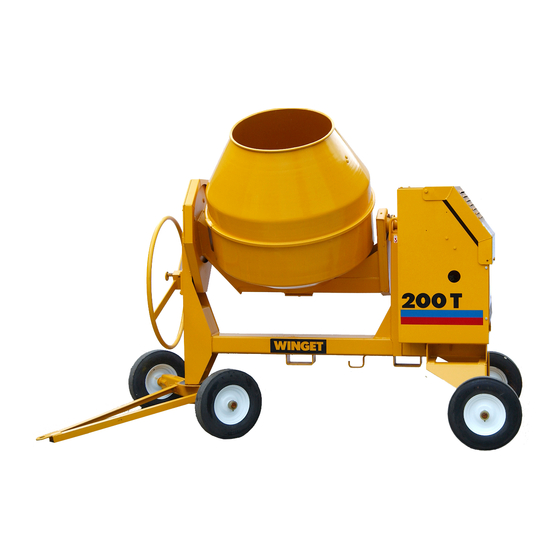
200T MIXER
OPERATORS HANDBOOK
&
PARTS
Manual V602069
printed May 2011
)
(This publication includes Manual WMANS544
Up to Machine Serial No 1332
WINGET LIMITED, P.O. Box 41, Edgefold Industrial Estate, Plodder Lane, Bolton, BL4 0LS, England
Tel: +44 (0) 1204 854650
Fax: +44 (0) 1204 854663
www.winget.co.uk
Advertisement
Table of Contents

Related Manuals for Winget 200T


Summary of Contents for Winget 200T
- Page 1 Manual V602069 printed May 2011 (This publication includes Manual WMANS544 Up to Machine Serial No 1332 WINGET LIMITED, P.O. Box 41, Edgefold Industrial Estate, Plodder Lane, Bolton, BL4 0LS, England Tel: +44 (0) 1204 854650 Fax: +44 (0) 1204 854663 www.winget.co.uk...
-
Page 2: Table Of Contents
INTRODUCTION CONTENTS Section Page Section Page TECHNICAL INFORMATION INTRODUCTION Introduction Lubricants Warranty Noise levels Safe Working Drum speed Mixer drum sealant Decals Engines & motors Lashing down & lifting points Dimensions OPERATION Electrically driven mixers wiring Yanmar L40/L48 ARE-SE Installation key start wiring Lister-Petter LT1/LV1-10 engines Yanmar L40/L48 ARE-SE... -
Page 3: Introduction
The contents of this Handbook, although correct at the time of publication may be subject to alteration by the Manufacturers without notice. Winget Limited operate a policy of continuous product development. Therefore, some illustrations or text within this publication may differ from your machine. -
Page 4: Warranty
No claim will be considered if other than genuine Winget Limited parts, which must be obtained from Winget Limited via an authorised Distributor, are used to effect a repair, or if lubricants other than those recommended by Winget Limited are used. - Page 5 INTRODUCTION...
- Page 6 SAFE WORKING Safety is the responsibility of the persons working with this machine. Think “safety” at all times. Read and remember the contents of this Handbook MACHINE MODIFICATION Any modifications to the machine will affect its working parameters and safety factors.
- Page 7 SAFE WORKING ENGINE Starting any diesel engine can be dangerous in the hands of inexperienced people. Operators must be instructed in the correct procedures before attempting to start any engine. Always obtain advice before mixing oils; some oils are not compatible. If in doubt, drain and refill.
- Page 8 SAFE WORKING SERVICING & MAINTENANCE Never allow unqualified personnel to attempt to remove or replace any part of the machine, or anyone to remove large or heavy components without adequate lifting equipment. Before maintenance work is begun, ensure that the engine is stopped, or that the electric motor is switched off, and isolated from the mains.
-
Page 9: Safe Working
SAFE WORKING Battery isolator. Remove starting handle. Beware of electrical hazards. Wear ear protection. Engine stop. Wear eye protection. Keep clear of chain drives. Conforms to EEC standards. These surfaces may be hot. Keep hands clear of drum. - Page 10 SAFE WORKING...
-
Page 11: Lashing Down & Lifting Points
SAFE WORKING Lashing down & lifting points General Care should be taken when lifting or transporting the mixer to ensure that lifting or retaining straps are in good condition and the following procedures must be followed when lifting or lashing down to avoid causing unnecessary damage. - Page 12 SAFE WORKING Lashing down The drum should be locked upright position, as illustrated, to keep the centre of gravity as low as possible. It is recommended that unless the mixer is pulled up against a headboard or some form of substantial wheel chocks that two ratchet type webbing straps are used to retain the mixer, one pulling to the rear and one pulling to the front.
- Page 13 SAFE WORKING...
-
Page 14: Operation
OPERATION Installing the mixer on site Check that the lubricating oil level is Welded to the mixer are lifting points. correct. The oil sump must be filled to the These are provided to assist with loading ‘full’ mark on the dipstick; do not overfill. unloading mixer transportation across site. - Page 15 OPERATION LT1-10/LV1-10 engines Description A Dipstick B Lubricating oil filler C Engine control D Decompressor lever F Fuel tank The cold start aid (where fitted) The cold start aid is fitted to the combustion air intake port and is used when the ambient temperature is below -10 deg.C (14 deg.F).
- Page 16 OPERATION Ensure there are no burrs on the handle. Before attempting to use the handle, clean and lightly oil that part of it which fits onto the engine. Hand starting the engine Select the excess fuel position by gently pulling the engine control lever (L) outward over the middle catch (M) and turning it fully clockwise.
-
Page 17: Yanmar L40/L48 Are-Se
OPERATION Yanmar L40/L48 ARE-SE Description A Fuel cock B Engine speed lever E Starting key Electric starting the engine Open the fuel cock (A). Put the engine start lever to the RUN position (B). Turn the starting key (E) clockwise to START position. - Page 18 OPERATION Yanmar L40/L48 ARE-SE Stopping the engine Return the engine speed lever to the STOP position. Note: On later engines it is necessary to depress the red button on the stop control to release this control into the STOP position. With electric-start engines, turn the starter key to the OFF position.
- Page 19 OPERATION Yanmar L40/L48 ARE-SE Manual starting in the event of a flat battery Description A Fuel cock B Engine speed lever C Decompression lever D Recoil starting handle Starting the engine Open the fuel cock (A). Put the engine start lever to the RUN position (B).
-
Page 20: Electric Motors
OPERATION Electric motors To start and stop: Gain access to start button by raising the motor cover (50). Start the motor by pressing button (51). Lower the motor cover (50). To stop the motor, press button (52). (Pressing button (53) will also stop it.) In an EMERGENCY, press button (52) to stop the motor. - Page 21 OPERATION Ensure that a suitable container has been positioned by the side of the mixer to catch the discharging load. Turn the drum to Discharge (2), and allow the load to run into the container. At the end of the working day A Thoroughly clean out the mixing drum with water and gravel.
-
Page 22: Servicing
SERVICING SERVICE SCHEDULE YANMAR L40 ENGINE (See also the relevant Engine Workshop Manual) For servicing the Yanmar L40/L48 engine, see the Every day engine Operation Manual Links & hinges: Lubricate. Shafts & bearings: Lubricate. Engine: Check fuel and lubricating oil levels. (see Engine Manual Check for oil and fuel leaks. -
Page 23: Greasing & Lubrication
SERVICING SERVICING PROCEDURE Drum drive Greasing and lubrication Every week (or 50 hours running) It is essential that oils and grease used for servicing do Lubricate drive chains (A) with a little not become contaminated engine oil. (Do not oil the belts of with sand or cement dust. -
Page 24: Bolt Torques
SERVICING Bolt torques Every week for the first month, then every three months Check the tightness of all bolts, nuts, and keys etc. Pay particular attention to engine mounting bolts. Engine, general servicing Under very dusty conditions, air cleaners, lubricating oil and fuel filters will require more frequent attention. -
Page 25: Engine Lubrication Oil
SERVICING Engine lubrication oil Every day Check lubrication oil level with the dipstick. Top up if necessary. Every 250 hours Drain and refill the oil sump as follows: Dispose of waste oil into waste oil storage tanks. If storage tanks are not available, consult your Distributor or local authority for addresses of local... - Page 26 SERVICING Fuel filter Every 250 hours or 500 hours (see schedule) Before changing the filter read the warnings in the "Safe working" section of this handbook. Change LT1-10/LV1-10 fuel filters as follows: Remove the retaining bolt or plug (H). Remove the old element (I) and joints (J).
-
Page 27: Battery
SERVICING Battery BATTERIES CONTAIN SULPHURIC ACID WHICH CAN CAUSE SEVERE BURNS AND PRODUCE EXPLOSIVE GASES. If the acid has been splashed on the skin, eyes or clothes flush with copious amounts of fresh water and seek immediate medical aid. Check the battery as follows: Wear protective gloves and goggles. -
Page 28: Mixer Drum Assembly
513204000 can be obtained from any Winget distributor.) A Bolt the two blades into the drum base (1). Tighten the bolts with fingers only. Smear silicone sealant around the mating flanges of the cone (2) and drum base (3). - Page 29 SERVICING G Locate the clamping tool (7) into the two holes (8) of the drum clip. Tighten the tool securely using a suitable spanner. H Centralise the bridge piece (9) on the drum clip between the jaws of the clamping tool. 1 Weld the bridge piece (9) to the drum clip (5).
-
Page 30: Mixer Drum Drive Overhaul
SERVICING Mixer drum drive overhaul D The bevel pinion assembly (d) must be set horizontally in the trunnion. Do this On reassembling the drum drive, after an as follows: overhaul, the following points must be Ensure that the drive chain (f) is observed: correctly adjusted, then set the bevel Note: It is important to pack all sealed... - Page 31 3.10 SERVICING...
-
Page 32: Technical Information
TECHNICAL INFORMATION Lubricants Mixers are factory filled with the following TOTAL oils. Engine, LT1/LV1-10: lubricating oil Rubia B 10W/30 1.3 litres Yanmar L40/48: lubricating oil Rubia B 10W/30 0.8 litres Note: In cold weather engines are to be filled with 10W oil to aid starting. LT1/LV1-10: fuel 5.0 or 8.25 litres Yanmar L40/48: fuel... -
Page 33: Dimensions
TECHNICAL INFORMATION Dimensions A Overall length 2208 mm B Overall width 1320 mm C Overall height 1825 mm D Loading height 1130 mm E Discharge height 660 mm -- Weight (approx) 600 kg... -
Page 34: Electrically Driven Mixers Wiring
TECHNICAL INFORMATION Electrically driven mixers wiring circuit Electrical connections must only be made by a suitably qualified electrician. -
Page 35: Yanmar L40/L48 Are-Se Key Start Wiring
TECHNICAL INFORMATION Yanmar L40/L48 ARE-SE key start wiring circuit In addition to the circuit shown below, the engine is fitted with its own loom. (see Yanmar service literature) - Page 36 Mixers manufactured UP TO serial number T200DL0547 (November 1993) Mixers manufactured FROM serial number T200DL0548 (November 1993) <<< TO BEGINNING OF BOOK...
- Page 37 Mixers manufactured up to serial number T200DL0547 (November 1993)
- Page 38 CONTENTS A - 1 MAINFRAME B - 1 DRUM & TRUNNION C - 1 LISTER, drive assembly C - 2 PETTER, drive assembly C - 3 ELECTRIC MOTOR, drive assembly C - 4 START/STOP SWITCHES, electric drive D - 1 DECALS &...
- Page 39 A - 1 200T Mixer (up to serial number T200DL0548)
- Page 40 A - 1 MAINFRAME Item Part no Serial no Description 1 513315100 / 0548 PIN, swivel 2 10S31 WASHER, flat 3 353308200 PIN, split 4 513315200 TOWBAR 5 63SO2K BOLT 6 513324700 COLLAR, axle 7 7S02 8 17S03 WASHER, spring 9 1 1S05D SCREW, set 10 61S05...
- Page 41 B - 1 200T Mixer (up to serial number T200DL0548)
- Page 42 B - 1 DRUM & TRUNNION Item Part no Serial no Description 1 513315400 / 0548 HANDWHEEL 2 352806100 PIN, mills 3 513194400 PLUNGER 4 304708040 KEY, feather 5 403751016 SCREW, set 6 513315600 BEARING, handwheel 7 513315900 PLATE, backing 8 112803400 BUSH 9 513316000...
- Page 43 B - 1 200T Mixer (up to serial number T200DL0548)
- Page 44 B - 1 DRUM & TRUNNION Item Part no Serial no Description 42 11S03B / 0548 SCREW, set 43 17S04 WASHER, spring 44 7S03 45 11S04B SCREW, set 46 17S05 WASHER, spring 47 7S04 48 300110845 KEY, taper gib head 49 132775000 CIRCLIP 50 88S45D...
- Page 45 C - 1 200T Mixer (up to serial number T200DL0548)
- Page 46 C - 1 DRIVE ASSEMBLY, LISTER Item Part no Serial no Description 1 354051000 / 0548 ENGINE, LISTER LT1 2 513326400 SPROCKET, engine 3 300204160 KEY, gib head 4 513248400 SHIMS 1 set 5 8S05J BOLT 6 8S05E BOLT 7 61S05 NUT, locking 8 267S07 WASHER, flat...
- Page 47 C - 2 200T Mixer (up to serial number T200DL0548)
- Page 48 C - 2 DRIVE ASSEMBLY, PETTER Item Part no Serial no Description 354074900 / 0548 ENGINE, PETTER AC1ZS 513267600 CHANNEL, engine mount 513248400 SHIMS 1 set 8S04E BOLT 61S04 NUT, locking 267S06 WASHER, flat 105S04 WASHER, taper 8SO5F BOLT 61S05 NUT, locking 267S07 WASHER, flat...
- Page 49 C - 3 200T Mixer (up to serial number T200DL0548)
- Page 50 C - 3 DRIVE ASSEMBLY, ELECTRIC Item Part no Serial no Description 1 513335900 PLATE, motor mounting 2 513336000 SUPPORT, motor mounting 3 513333100 STUD, motor adjusting 4 513333500 PULLEY, 'V' 5 513336100 GUARD, pulley 7 11S05D SCREW, set 8 59S04 NUT, nylon insert 9 8S05E BOLT...
- Page 51 C - 4 200T Mixer (up to serial number T200DL0548)
- Page 52 C - 4 SWITCHES & CABLES, Electric drive assembly Item Part no Serial no Description 1 208392500 SWITCH, " Start / Stop 2 16SO6C SCREW 3 267S03 WASHER, flat 4 17S02 WASHER, spring 5 7S01 6 205103400 SWITCH, " Stop " OBSOLETE: use 208880000 6 208870000 / Oct-04...
- Page 53 D - 1 200T Mixer (up to serial number T200DL0548)
- Page 54 D - 1 DECALS & PLATES Item Part no Serial no Description 1 V2003110 200T 2 10317A05 PLATE, serial (OBSOLETE: use V2003037) 2 V2003037 PLATE, serial --- 15S01A SCREW 3 504600900 WARNING, engine housing 4 504694600 WARNING, safety 5 513331500...
- Page 55 D - 3 200T Mixer (up to serial number T200DL0548)
- Page 56 D - 3 SPECIAL TOOLS Item Part no Serial no Description 1 513204000 CLAMP, drum clip V601137 / Dec '93...
- Page 57 Numerical Index <<< TO BEGINNING OF SECTION...
- Page 58 Part No. Page Part No. Page Part No. Page 112803400 B - 1 241902000 C - 1 513198500 A - 1 131270000 C - 4 241908000 C - 2 513204000 D - 3 131271000 C - 4 300110845 B - 1 513205300 A - 1 131570016...
- Page 59 Part No. Page Part No. Page Part No. Page 513315600 B - 1 513336100 C - 3 17S02 C - 4 513315900 B - 1 513337900 C - 1 17S03 A - 1 513316000 B - 1 515175000 D - 1 17S03 B - 1 513316300...
- Page 60 Part No. Page 7S02 A - 1 7S03 A - 1 7S03 B - 1 7S03 C - 3 7S04 B - 1 7S04 C - 1 7S04 C - 2 7S05 B - 1 7S05 C - 3 88S05D B - 1 88S42D B - 1...
- Page 61 Mixers manfactured from serial number T200DL0548 (November 1993)
- Page 62 CONTENTS A - 1 MAINFRAME & FRONT AXLE A - 2 PANELS B - 1 DRUM B - 2 TRUNNION & TILT WHEEL B - 3 DRUM DRIVE C - 1 LISTER- PETTER LT1-10/LV1-10, engine C - 2 ELECTRIC MOTOR, drive assembly C - 3 START / STOP SWITCHES, electric drive mixer C - 5...
- Page 63 A - 1 200T Mixer MCH-29...
- Page 64 A - 1 MAINFRAME & FRONT AXLE Item Part no Serial no Description 1 513357100 MAINFRAME 5 513324900 AXLE, front 6 353308200 PIN, split 7 10S31 WASHER, flat 8 513315100 PIN, swivel 10 513315200 BAR, towing 11 61S05 NUT, self-locking 12 11S05D SCREW, set 15 475115000...
- Page 65 A - 2 200T Mixer MCH-28...
- Page 66 A - 2 PANELS Item Part no Serial no Description (year) / 1993 1 V2003568 BOX, document (document box now welded to item 45) 2 101S07E (year) / 1993 RIVET 5 513326000 PLATE 6 52S02C SCREW, counter sunk head 7 11S03A SCREW, set 8 17S04 WASHER, spring...
- Page 67 B - 1 200T Mixer MD-16...
- Page 68 B - 1 DRUM Item Part no Serial no Description 1 513323902 DRUM, top 2 513324000 DRUM, base 3 513324100 CLIP, drum 4 513324200 BRIDGE PIECE 5 V2000772 ADHESIVE, flexible tube 1 10 513324300 BLADE 11 16S09D SCREW, slottted panhead 12 17S05 WASHER, spring 13 7S04...
- Page 69 B - 2 200T Mixer MD-17...
- Page 70 B - 2 TRUNNION & TILT WHEEL Item Part no Serial no Description 1 513354000 TRUNNION 3 513316600 COVER, rear 4 11S02AA SCREW, set 5 17S03 WASHER, spring 6 131S01 NIPPLE, grease 7 176S01 CAP, nipple 8 315803100 NIPPLE, grease 10 513316500 GUARD, drum gear 11 11S03B...
- Page 71 B - 3 200T Mixer MD-15...
- Page 72 B - 3 DRUM DRIVE Item Part no Serial no Description 1 300110845 KEY, taper gib 2 513310700 PINION 3 132362000 CIRCLIP 4 88S05D BEARING 5 513310300 SHAFT 6 513305400 HOUSING 7 88S15D BEARING 10 513152400 SHIM, pack set 1 11 513324400 WASHER, locking strip 12 11S05H...
- Page 73 C - 1 200T Mixer ELP-30...
- Page 74 C - 1 LISTER-PETTER LT1/LV1-10 engine Item Part no Serial no Description 1 354051000 / 1013 ENGINE, LT1-10 "Export" without anti kickback 1 354051000 1014 / ENGINE, LV1-10 "Export" without anti kickback 1 354054100 / 1013 ENGINE, LT1-10 "UK/EEC" with anti kickback 1 354054100 1014 / ENGINE, LV1-10...
- Page 75 C - 1 200T Mixer...
- Page 76 C - 1 LISTER-PETTER LT1/LV1-10 engine Item Part no Serial no Description 23 241902000 / 0609 FITTING, straight, female 23 241904000 0610 / 0969 FITTING, straight, female …………….. / 0969 PLUG, oil drain (See Eng. Parts Cat.) 24A 513362800 0970 / HOSE, flexable 24B 100S04 0970 /...
- Page 77 C - 2 200T Mixer MEL-...
- Page 78 C - 2 DRIVE ASSEMBLY, electric Item Part no Serial no Description 1 202438000 MOTOR, electric 2 11S04D SCREW, set 3 7S04 4 17S05 WASHER, spring 5 304710840 KEY, parallel 6 57S04D2 SCREW, grub 7 513333500 PULLEY, vee 8 397400100 BELT, vee 10 513335900 PLATE, motor mounting...
- Page 79 C - 3 200T Mixer MEL-23...
- Page 80 C - 3 START / STOP SWITCHES, electric drive mixers Item Part no Serial no Description 1 208392500 SWITCH, “ Start / Stop ” 2 16S06C SCREW 3 267S03 WASHER, flat 4 17S02 WASHER, spring 5 7S01 6 208870000 / Oct-04 # SWITCH, stop, assembly # OBSOLETE: use 208880000 6A V602651...
- Page 81 C - 5 200T Mixers from October 2000 ELP-37...
- Page 82 C - 5 YANMAR L40/L48 ARE-SE (electric start) Engine & mounts Item Part no Serial no Description Note: For Battery, start switch & loom, see page C-6 1 V2005210 0844 / ENGINE, Yanmar L40/L48 ARE-SE 2 513361600 PIPE, exhaust 3 153S02 CLAMP, exhaust 4 267S04 WASHER, flat...
- Page 83 C - 6 200T Mixers from October 2000 ELP-37...
- Page 84 C - 6 YANMAR L40/L48 ARE-SE (electric start) Battery, start switch & loom Item Part no Serial no Description 26 V2005211 0844 / CABLE, negative 35 267S07 WASHER, flat 36 17S06 WASHER, spring 37 7S05 60 109S11 BATTERY, 12 volt 61 11S02B SCREW, set 62 267S04...
- Page 85 D - 1 200T Mixer...
- Page 86 D - 1 DECALS & PLATES Item Part no Serial no Description 1 V2003110 “200T” 2 V2003037 PLATE, serial number 15S01A SCREW 3 504600900 WARNING, engine housing 4 504694600 WARNING, safety 5 V2003039 LOGO, “WINGET” 6 V2003038 STRIPE, bodywork 6A V2005276...
- Page 87 D - 1A 200T Mixer...
- Page 88 D - 1A DECALS & PLATES Item Part no Serial no Description 10 V2004302 ENGINE STOP 11 V2004307 ELECTRICAL HAZARD 12 V2004137 EAR PROTECTION 13 V2004744 EYE PROTECTION 14 V2004227 BATTERY ISOLATOR 15 V2004229 OPERATORS HANDBOOK 16 V2004282 HOT SURFACES 17 V2004289 HANDS CLEAR 18 V2005208...
- Page 89 D - 1B 200T Mixer...
- Page 90 D - 1B DECALS & PLATES Item Part no Serial no Description 26 V2005311 101 LWA 27 V2004130 80 LpA 28 V2004297 98 LWA 29 V2005290 STOP ENGINE WITH RED BUTTON 30 V2005291 TRANSPORTING WITH FORKS 31 V2005214 RECOIL STARTER WARNING V601191 / June '03...
- Page 91 D - 2 200T Mixer MMI - 15...
- Page 92 D - 2 SPECIAL TOOLS Item Part no Serial no Description 1 513204000 CLAMP, drum clip V601191 / issue 01 0993...
- Page 93 Numerical Index <<< TO BEGINNING OF SECTION...
- Page 94 Part No. Page Part No. Page Part No. Page 112803400 B - 2 254820000 C - 5 513298900 B - 3 131271000 C - 3 300110845 B - 3 513305200 B - 1 131570016 C - 3 300110845 B - 3 513305300 B - 3 131766010...
- Page 95 Part No. Page Part No. Page Part No. Page 513325800 A - 2 11S01C C - 3 16S09D B - 1 513326000 A - 2 11S02A A - 2 176S01 B - 2 513326300 B - 1 11S02A A - 2 17S02 C - 3 513326400...
- Page 96 Part No. Page Part No. Page Part No. Page 267S07 C - 1 7S03 B - 2 V2004132 D - 1A 267S07 C - 2 7S04 A - 2 V2004137 D - 1A 267S07 C - 5 7S04 B - 1 V2004220 C - 5 267S07...
- Page 97 CALIFORNIA Proposition 65 Warning Diesel engine exhaust and some of its constituents are known to the state of California to cause cancer, birth defects, and other reproductive harm.
Need help?
Do you have a question about the 200T and is the answer not in the manual?
Questions and answers