Advertisement
Quick Links
FLEX
S
E
I
I
HOWER
NCLOSURE
NSTALLATION
NSTRUCTIONS
IMPORTANT
DreamLine
reserves the right to alter, modify or redesign products at any time without prior
TM
notice. For the latest up-to-date technical drawings, manuals or any other details please refer
to the
support.BathAuthority.com
web page.
Please read these instructions carefully before installing. If you have any questions regarding
installation, please call our technical support specialists Monday through Friday 9:00 AM – 5:00
PM EST at Phone: 1-866-731-2244, Fax:
1-866-227-1533
or e-mail our technical support group
support@BathAuthority.com.
at
TM
For more information on
DreamLine
Shower Enclosure
please visit
www.BathAuthority.com
Advertisement

Related Manuals for Dreamline FLEX


Summary of Contents for Dreamline FLEX
- Page 1 FLEX HOWER NCLOSURE NSTALLATION NSTRUCTIONS IMPORTANT DreamLine reserves the right to alter, modify or redesign products at any time without prior notice. For the latest up-to-date technical drawings, manuals or any other details please refer to the support.BathAuthority.com web page.
-
Page 2: Tools Required
Shower Door Components”. Examine boxes and packages for shipping damage. If the unit has been damaged, has a finishing defect, or is missing parts, please contact our customer support department within 5 business days of the delivery date. Please note that DreamLine will not replace any damaged products or missing parts free of charge after 5 business days or if the product has been installed. - Page 3 Before discarding the carton, check for small hardware bags that tend to fall to the bottom of the box. If any parts are damaged or missing, please contact DreamLine for replacement. NOTE: Retain these installation instructions for future reference. “FLEX” Enclosure Rev.1, Ver.3 03/2014...
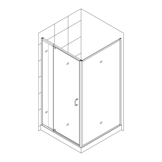
- Page 4 Door Assembly Diagram Alluminum profile Return Wall profile Stationary glass Return Glass panel Expandable rail Corner profile Glass door Alluminum profile Expandable rail “FLEX” Enclosure Rev.1, Ver.3 03/2014...
- Page 5 Shower base or threshold against the finished wall and level it vertically. See Fig. 2 and table below for details. Model No. 30 1/2" 28 1/2" - 32 1/2" SHDR-2230300-RT-01 SHDR-2234340-RT-01 34 1/2" 32 1/2" - 36 1/2" “FLEX” Enclosure Rev.1, Ver.3 03/2014...
- Page 6 Apply a bead of silicone to the wall along the drilled holes and around the holes. Attach the Return wall profile to the wall with the Round head screws ST4.2×40 (05). See Fig. 4 and Fig. 5 for details. Ø 5/16" “FLEX” Enclosure Rev.1, Ver.3 03/2014...
- Page 7 Corner profile. Secure the Corner profile to the Return glass panel with the Round head screws ST4.2×10 (04). Set this Return glass panel assembly aside. Ø 1/8" See fig. 6 and Fig. 7 for details. “FLEX” Enclosure Rev.1, Ver.3 03/2014...
- Page 8 6. Install the Handle (13) onto the Door assembly (02). Move the Door assembly onto the Shower base and slide the Stationary glass side into the Wall profile (01). See Fig. 8 and Fig. 9 for details. “FLEX” Enclosure Rev.1, Ver.3 03/2014...
- Page 9 7. Slide the Return glass panel (09) assembly into the groove of the Return wall profile (11). See Fig. 10 for details. . 10 “FLEX” Enclosure Rev.1, Ver.3 03/2014...
- Page 10 Corner profile (10). Insert Glass door side into the Corner profile. NOTICE: The maximum adjustable length of the Expanding rails is: 4 1/2" See Fig. 11 and Fig. 12 for details. . 11 . 12 “FLEX” Enclosure Rev.1, Ver.3 03/2014...
- Page 11 Ø 1/8" only the first layer. Secure the Expanding rails using Round head screws ST4.2×10 (04) with the raised white washers. Cover exposed screw heads with Decorative covers (06). See Fig. 14 for details. . 14 “FLEX” Enclosure Rev.1, Ver.3 03/2014...
- Page 12 Secure the Door assembly inside the Corner profile using the Round head screws ST4.2×10 (04) with the raised white washers. Cover the exposed screw heads with the Decorative covers (06). See Fig. 16 for details. . 16 “FLEX” Enclosure Rev.1, Ver.3 03/2014...
- Page 13 Wall profile (01), Return wall profile (11), bottom Expanding rail and the base of the Return glass panel (09) from both inside and outside the shower. See Fig. 18 for details. Waterproof Silicone . 18 “FLEX” Enclosure Rev.1, Ver.3 03/2014...
-
Page 14: Product Maintenance
Clean stainless steel surfaces at least once a week. When applying stainless steel cleaner or polish, work with (not against) the grain. Never use an abrasive sponge or cloth, steel wool or wired brushes. “FLEX” Enclosure Rev.1, Ver.3 03/2014... - Page 15 ™ EXCLUSIVE LIMITED WARRANTY AS OF MAY 6, 2013 DREAMLINE This warranty extends only to the original owner/end‐user for household use only and is not transferable to a subsequent owner. This warranty extends for a designated period of time, so long as it remains in use in its original place of installation. This warranty applies only to DreamLine products purchased from an authorized dealer in United States or Canada. Proof of purchase (original sales receipt) from the original consumer purchase must be provided with all warranty claims. IN NO EVENT SHALL THE LIABILITY OF DREAMLINE EXCEED THE PURCHASE PRICE OF THE UNIT. DreamLine products must be installed by a fully insured and licensed professional. Installation of DreamLine product by anyone other than fully insured licensed professionals shall VOID THE WARRANTY. DreamLine recommends that such licensed professionals have experience in the installation of bathroom products. Installation of certain products, including, without limitation, ...
- Page 16 TEL: 866-731-2244 FAX: 866-227-1533 WWW. UTHORITY.COM For more information on DreamLine Shower Enclosure please visit www.BathAuthority.com...
Need help?
Do you have a question about the FLEX and is the answer not in the manual?
Questions and answers