Helios ultraSilence ELS-GUB Series Installation And Operating Instrucitons
Hide thumbs
Also See for ultraSilence ELS-GUB Series:

Related Manuals for Helios ultraSilence ELS-GUB Series


Summary of Contents for Helios ultraSilence ELS-GUB Series
- Page 1 Helios Ventilatoren MONTAGE- UND BETRIEBSVORSCHRIFT NR. 19 104 Kunststoffgehäuse ¬ mit Brandschutzummantelung und Brandschutz- absperrvorrichtung ELS-GUB.. (Unterputz)
- Page 2 Korrekte Entsorgung dieses Produktes (Elektromüll) Die Kennzeichnung auf dem Produkt bzw. auf der dazugehörigen Montage- und Betriebsvorschrift gibt an, dass es nach seiner Lebensdauer nicht zusammen mit dem normalen Haushaltsmüll entsorgt werden darf. Entsorgen Sie dieses Gerät bitte getrennt von anderen Abfällen, um der Umwelt bzw. der menschlichen Gesund- heit nicht durch unkontrollierte Müllbeseitigung zu schaden.
-
Page 3: Table Of Contents
Montage- und Betriebsvorschrift Gehäuse-Typen ELS-GUB.. Inhaltsverzeichnis KAPITEL 1. ELS-SCHNELLÜBERSICHT ............Seite 2 Typenübersicht der Unterputzgehäuse mit Brandschutzabsperrvorrichtung . -
Page 4: Els-Zubehör
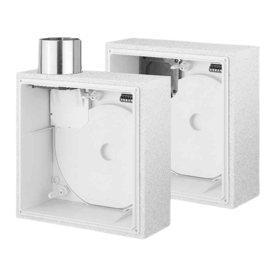
Montage- und Betriebsvorschrift Gehäuse-Typen ELS-GUB.. Typenübersicht Unterputzgehäuse mit Brandschutzummantelung und Brandschutzabsperrvorrichtung KAPITEL 1 ELS-GUB.. ELS-GUBR.. ¬ ¬ ELS-SCHNELLÜBERSICHT Unterputzgehäuse mit Unterputzgehäuse mit Brandschutz-Ummantelung Brandschutz-Ummantelung Metall-Ausblasstutzen, oben Metall-Ausblasstutzen, rück- seitig Best.Nr. 8112 Best.Nr. 8113 SEITE 6 SEITE 6 1.1 ELS-Zubehör ELS-ARS ELS-MHU Umbauset zum Einbau in Montagehalter, Unterputz... -
Page 5: Wichtige Informationen
Wenn die nachfolgenden Ausführungen nicht beachtet werden, entfällt unsere Gewährleistung. Gleiches gilt für Haf- tungsansprüche an den Hersteller. Der Gebrauch von Zubehörteilen, die nicht von Helios empfohlen oder angeboten werden, ist nicht statthaft. Even tuell auftretende Schäden unterliegen nicht der Gewährleistung. -
Page 6: Brandschutz
Länge der Ausblasleitung über 1,5 m und einer Geschosshöhe über 2,75 m erhöhte Druckverluste entstehen, die durch größeren Querschnitt der Hauptleitung ausgeglichen werden müssen. Zur Dimensionierung kann die Helios-ELS-Software eingesetzt werden. Erhältlich über die Helios Website: www.heliosventilatoren.de. -
Page 7: Einbauort-/Position
Montage- und Betriebsvorschrift Gehäuse-Typen ELS-GUB.. ELS-GUB.. Kunststoffgehäuse mit Brandschutzummantelung und Brandschutzabsperrvorrichtung KAPITEL 3 – geeignet zum Einbau in Gebäude mit Brandschutzanforderung K90 und qualifiziertem Brandschutzschacht. Einbau in den qualifizierten Brandschutzschacht. Ausblas oben und um 90° zur Seite nach links oder rechts drehbar. ELS-LIEFERUMFANG UND EINBAU Lieferumfang / Verpackungseinheit, Abb.1-2... -
Page 8: Einbaulage
Montage- und Betriebsvorschrift Gehäuse-Typen ELS-GUB.. Einbaulage (nach links bzw. rechts 90° gedreht). HINWEIS Ausblasstutzen mit luftdichter Rückluft-Sperrklappe um 90° drehen. Zum Wechseln der Ein- ELS-GUB ELS-GUB Ausblasstutzen baulage, Schrauben des oben ˜ Ausblassstutzen lösen! Rückholfeder Ausblas- entfernen! (siehe Abb. 28) stutzen links 90°... - Page 9 Montage- und Betriebsvorschrift Gehäuse-Typen ELS-GUB.. Montagehalter ELS-MHU für Gehäuse ELS-GUB.. montieren Erforderlich für Unterputzmontage von ELS-GUB.. im Schacht, bei dünnen Vormauerungen, Beplankung oder Decke. Nachträgliches Justieren Einbauposition entsprechend der Gegebenheiten durch Lösen der seitlichen Schrauben (Abb. 8) in den Schlitzlöchern des Montagehalters in Höhe und Tiefe ausrichten.
-
Page 10: Montagebügel Els-Mb Für Vorwandsysteme Montieren
Montage- und Betriebsvorschrift Gehäuse-Typen ELS-GUB.. Montagebügel ELS-MB für Vorwandsysteme montieren Lieferumfang: Œ Montagebügel Sechskantschraube 2x Sechskantmutter 2x Wanddübel, Schrauben bauseits! HINWEIS Die Befestigung am Vorwandsystem erfolgt mit Vorwandsystemeigenen Winkeln bzw. Wandhaltern (Pos a.). Abb.12 Abb.13 Œ ... -
Page 11: Els-Einbaubeschreibung Für Beplankte Wand
Montage- und Betriebsvorschrift Gehäuse-Typen ELS-GUB.. ELS-Einbaubeschreibung für beplankte Wand 1. Um beim Einbau die Positionierung des Gehäuses auf der Wand zu vereinfachen, sind auf dem Gehäusesteg vier Andruck-Pins angebracht (siehe Abb. 18/19). Sie dienen zur Markierung des Gehäuseumrisses. 2. Das Gehäuse in der gewünschten Position an der beplankten Wand ausrichten und durch einen leichten Schlag auf die Rückseite markieren (siehe Abb. -
Page 12: Montage Putzblende Els-Pb
Montage- und Betriebsvorschrift Gehäuse-Typen ELS-GUB.. Montage Putzblende ELS-PB Die ELS-PB Putzblende dient zur Abdeckung von Spalten aufgrund unsauber eingeputzer/gefliester oder zu großer Gehäuseausschnitte, die von der Innenfassade nicht mehr abgedeckt werden. Die Blende wird zwischen Wand bzw. Decke und Innenfassade eingespannt. Abb.24 Abb.25 Maße in mm... -
Page 13: Ventilgehäuse
Montage- und Betriebsvorschrift Gehäuse-Typen ELS-GUB.. Ventilgehäuse mit luftdichter Rückluft-Sperrklappe – aus Metall inkl. Rückholfeder (siehe Abb. 30/31). Hinweis: Bei vertikalem Einbau muss die Rückholfeder entfernt werden! HINWEIS Rückholfeder einfach an den Federschenkeln (z.B. mit Spitzzange) herausziehen (siehe Abb. 31). Abb.30 Abb.31 Rückholfeder entfernen! -
Page 14: Schaltplan-Übersicht Für Els V
Montage- und Betriebsvorschrift Gehäuse-Typen ELS-GUB.. Schaltplan-Übersicht für ELS V.. Ventilator-Serien. Das zutreffende Verdrahtungsschema für die vorgesehenen Ventilatoren bitte ankreuzen! V 60 SS-869 V 100 SS-870 V 60/35 SS-871 V 100/35 SS-872 V 100/60 SS-873 1 2 3 L N 1 2 3 L N 1 2 3 L N 1 2 3 L N 1 2 3 L N... - Page 15 When used in combination with a DSEL 3 controller a lamp must not be connected. Dauerphase bei Pour l'utilisation du DSEL3, Permanent life for Helios Type aucune lampe ne peut Alimentation permanente pour DSEL3 être raccordée. ELS VN, VNC, VF Typen SS-903 85052 001 SS-903 17.12.07...
- Page 16 Service und Information HELIOS Ventilatoren GmbH & Co · Lupfenstraße 8 · 78056 VS-Schwenningen HELIOS Ventilateurs · Le Carré Aviateurs · 157 av. Charles Floquet · 93155 Le Blanc Mesnil Cedex CH HELIOS Ventilatoren AG · Tannstrasse 4 · 8112 Otelfingen GB HELIOS Ventilation Systems Ltd.
- Page 17 Helios Ventilatoren INSTALLATION AND OPERATING INSTRUCTIONS Flame retardant polymer casing ¬ with fire protection encasement and fire protection shutter ELS-GUB.. (flush mounted)
- Page 18 Korrekte Entsorgung dieses Produktes (Elektromüll) Die Kennzeichnung auf dem Produkt bzw. auf der dazugehörigen Montage- und Betriebsvorschrift gibt an, dass es nach seiner Lebensdauer nicht zusammen mit dem normalen Haushaltsmüll entsorgt werden darf. Entsorgen Sie dieses Gerät bitte getrennt von anderen Abfällen, um der Umwelt bzw. der menschlichen Gesund- heit nicht durch unkontrollierte Müllbeseitigung zu schaden.
- Page 19 Installation and Operating Instructions Fan-casing-type ELS-GUB.. Contents CHAPTER 1. ELS QUICK OVERVIEW ............page 2 Overview of types: Flush mounted casings with fire protection shutter .
- Page 20 Installation and Operating Instructions Fan-casing-type ELS-GUB.. Overview of types: flush mounted casing with fire protection encasement and fire protection shutter CHAPTER 1 ELS-GUB.. ELS-GUBR.. ¬ ¬ ELS- Flush mounted case with Flush mounted case with QUICK OVERVIEW fire protection coating, fire protection coating, metal-discharge above metal-discharge to the back...
-
Page 21: Important Information
Air dampers are not allowed. The diameter of the main line can be determined with the dimensioning pattern (of Helios main catalogue). Besides, it is to be noted that with a length of the extract air duct over 1,5 m and a storey height over 2,75 m increased pressure losses develop, which must be compensated by bigger cross section of the main line. -
Page 22: Fire Protection
Installation and Operating Instructions Fan-casing-type ELS-GUB.. FIRE PROTECTION Fire protection The references and regulations of the respectively valid certificates & examination reports are to be adhered to with fire protection casings and specified fire protection. An installation with discharge spigot at the bottom is not permitted. With arrangement of the casing outside of the funnel, the connecting duct must be from steel / flex. -
Page 23: Els-Gub
Installation and Operating Instructions Fan-casing-type ELS-GUB.. ELS-GUB.. flame retardant polymer casing with fire protection encasement and fire protection shutter CHAPTER 3 – suitable for installation in buildings with fire protection requirement K90 and qualified fire protection funnel. Installation in a qualified fire protection funnel. Discharge spigot lateral to the top and turnable to left or to the right by 90°. ELS-SHIPMENT AND INSTALLATION Scope of delivery / Packing unit, fig. -
Page 24: Fitting Position
Installation and Operating Instructions Fan-casing-type ELS-GUB.. Fitting position (turned to left or to the right by 90°). Turn discharge spigot with airtight backdraught shutter by 90° ELS-GUB ELS-GUB Discharge spigot at the top ˜ Remove Discharge return spring! spigot left 90°... -
Page 25: Installation Of Universal Mounting Bracket Els-Muh For Casing Els-Gub
2x hexagon head screw M6 x16 2x hexagon nut M6 ‘ 4x self-tapping screws M6x10 NOTE Wall-plugs, screws are not provided by Helios ! fig.6 fig.7 Ž Drill holes for scre entry in casing (Ø 6 mm) Mounting bracket Ž... -
Page 26: Installation Of Mounting Holder Els-Mb For Plasterboard Systems
Mounting holder 2x hexagon head screw 2x hexagon nut Wall-plugs, screws are not provided by Helios ! NOTE The fastening at the plasterboard system is carried out with plasterboard system specific brackets or wall holders (Pos.a). fig.12 fig.13 ... -
Page 27: Els Installation Description For Installation In Plasterboard
Installation and Operating Instructions Fan-casing-type ELS-GUB.. ELS installation description for installation in plasterboard 1. In order to simplify the positioning of the casing on the wall for the installation, four press pins are attached on the casing bar (see fig. 18/19). They serve for the marking of the casing outline. 2. -
Page 28: Wall- / Ceiling Installation Els-Gub
Installation and Operating Instructions Fan-casing-type ELS-GUB.. 4.6 Wall- / ceiling installation ELS-GUB Align desired position accurately and screw together fastening parts (mounting bracket ELS-MHU) firmly. Ins- NOTE erting sound isolated material at lightweight construction between ceiling and flush mounted casing. Wall fastening: fig.24 fig.25... -
Page 29: Connecting Duct (Flexible Duct Or Steal Duct)
With operation with fluorescent tubes, switch power supplies, electronically regulated halogen bulbs etc. these values can be exceeded. In this case additional suppression shielding activities (not provided by Helios) are necessary (L -, C or RC elements, protection diodes, resistors). -
Page 30: Wiring Diagram Overview For Els-V
Installation and Operating Instructions Fan-casing-type ELS-GUB.. Wiring diagram overview for ELS V.. fan series. Tick appropriate! V 60 SS-869 V 100 SS-870 V 60/35 SS-871 V 100/35 SS-872 V 100/60 SS-873 1 2 3 L N 1 2 3 L N 1 2 3 L N 1 2 3 L N 1 2 3 L N... - Page 31 DSEL 3 controller a lamp light must not be connected. Dauerphase bei Pour l'utilisation du DSEL3, Permanent life for Permanent live for Helios Type aucune lampe ne peut Alimentation permanente pour DSEL3 être raccordée. ELS VN, VNC, VF Typen SS-903 SS-904 SS-904 17.12.07...
- Page 32 Service und Information HELIOS Ventilatoren GmbH & Co · Lupfenstraße 8 · 78056 VS-Schwenningen HELIOS Ventilateurs · Le Carré des Aviateurs · 157 av. Charles Floquet · 93155 Le Blanc Mesnil Cedex CH HELIOS Ventilatoren AG · Tannstrasse 4 · 8112 Otelfingen GB HELIOS Ventilation Systems Ltd.
Need help?
Do you have a question about the ultraSilence ELS-GUB Series and is the answer not in the manual?
Questions and answers