
Related Manuals for Helios ultra Silence ELS-GU


Summary of Contents for Helios ultra Silence ELS-GU
- Page 1 Helios Ventilatoren MONTAGE- UND BETRIEBSVORSCHRIFT INSTALLATION AND OPERATING INSTRUCTIONS Kunststoffgehäuse ohne Brandschutz Plastic casing without fire protection ELS-GU (Unterputz) (flush-mounted)
- Page 2 Korrekte Entsorgung dieses Produktes (Elektromüll) Die Kennzeichnung auf dem Produkt bzw. auf der dazugehörigen Montage- und Betriebsvorschrift gibt an, dass es nach seiner Lebensdauer nicht zusammen mit dem normalen Haushaltsmüll entsorgt werden darf. Entsorgen Sie dieses Gerät bitte getrennt von anderen Abfällen, um der Umwelt bzw. der menschlichen Gesund- heit nicht durch unkontrollierte Müllbeseitigung zu schaden.
-
Page 3: Table Of Contents
Montage- und Betriebsvorschrift Gehäuse-Typen ELS-GU Inhaltsverzeichnis KAPITEL 1. ELS-SCHNELLÜBERSICHT ............Seite 2 Typenübersicht der Unterputzgehäuse . -
Page 4: Els-Zubehör
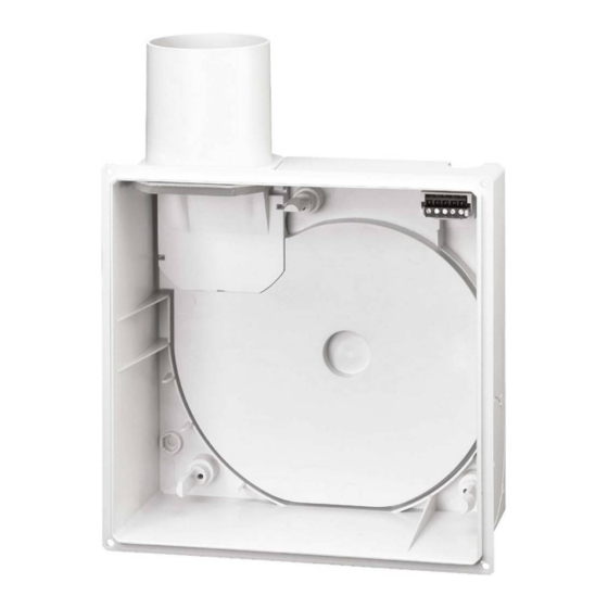
Montage- und Betriebsvorschrift Gehäuse-Typen ELS-GU Typenübersicht Unterputzgehäuse KAPITEL 1 ELS-GU ELS-SCHNELLÜBERSICHT Unterputzgehäuse Kunststoff Best.Nr. 8111 SEITE 5 1.1 ELS-Zubehör ELS-ARS ELS-AGR ELS-UPA Ausgleichsrahmen, zum Umbauset zum Einbau in Unterputz Ausgleichs- ELS-V... Ausblas rückseitig, Einspannen zwischen Wand rahmen zu UP-Gehäuse. bestehend aus Leitblech und Innenfassade, wenn Wird eingesetzt bei zu tief und 4 Kunststoffnieten für... -
Page 5: Wichtige Informationen
Wenn die nachfolgenden Ausführungen nicht beachtet werden, entfällt unsere Gewährleistung. Gleiches gilt für Haf- tungsansprüche an den Hersteller. Der Gebrauch von Zubehörteilen, die nicht von Helios empfohlen oder angeboten werden, ist nicht statthaft. Even tuell auftretende Schäden unterliegen nicht der Gewährleistung. -
Page 6: Elektrischer Anschluss
Länge der Ausblasleitung über 1,5 m und einer Geschosshöhe über 2,75 m erhöhte Druckverluste entstehen, die durch größeren Querschnitt der Hauptleitung ausgeglichen werden müssen. Zur Dimensionierung kann die Helios-ELS-Software eingesetzt werden. Erhältlich über die Helios Website: www.heli- osventilatoren.de. -
Page 7: Einbauort-/Position
Montage- und Betriebsvorschrift Gehäuse-Typen ELS-GU ELS-GU Kunststoffgehäuse ohne Brandschutz KAPITEL 3 – geeignet zum Einbau in Gebäude ohne Brandschutzanforderung gemäß LBO (Landesbauordnung). – geeignet zum Einbau in Gebäude mit Brandschutzanforderung K90 in Verbindung mit der Installation von Brand- ELS-LIEFERUMFANG UND schutzdeckenschott ELS-D. -
Page 8: Einbaulage
Montage- und Betriebsvorschrift Gehäuse-Typen ELS-GU Einbaulage (nach links bzw. rechts 90° gedreht). Ventilgehäuse mit Rücksperrklappe um 90° drehen. ACHTUNG In allen geänderten Einbaulagen muss das Wuchtgewicht Ó aufgesteckt werden. ELS-GU ELS-GU Ausblasstutzen ä oben Ausblas- Wuchtgewicht Ø stutzen entfernen! links ... -
Page 9: Umbau Els-Gu, Ausblas Rückseitig
Montage- und Betriebsvorschrift Gehäuse-Typen ELS-GU Umbau ELS-GU, Ausblas rückseitig - Zubehör ELS-ARS erforderlich. ELS-ARS wird zur Endmontage des Spiraleinsatzes benötigt. HINWEIS Im UP-Gehäuse aufbewahren, falls mitgeliefert. - Rampe (Position Í) hat keine weitere Verwendung! Abb.7 Abb.8 ä ë ö Abb.9 Abb.10 ä... -
Page 10: Umbau Zweitraumanschluss
Montage- und Betriebsvorschrift Gehäuse-Typen ELS-GU Umbau Zweitraumanschluss - Zubehör ELS-ZS oder ELS-ZAS erforderlich. HINWEIS Verbindungsleitung Aluflex/Stahlflex DN 80 luftdicht verbinden und abdichten. Abb.13 Abb.14 ELS-GU.. Ausblas oben, Anschluss für Zweitraum links oder rechts ELS-ZAS Öffnung für Stutzen im Anschluss- Unterputzkasten rechts stutzen anbringen. -
Page 11: Montagehalter Els-Mhu Für Up-Gehäuse Montieren
Montage- und Betriebsvorschrift Gehäuse-Typen ELS-GU Montagehalter ELS-MHU für UP-Gehäuse montieren Erforderlich für Unterputzmontage von ELS-GU im Schacht, bei dünnen Vormauerungen, Beplankung oder Decke. Lieferumfang: â Wandbügel ê Seitenschiene ô Montagebügel û 2x Sechskantschraube M6 x16 á 2x Sechskantmutter M6 é 4x Schrauben M6x10 (selbstschneidend) HINWEIS Wanddübel, Schrauben bauseits! -
Page 12: Montagebügel Els-Mb Für Vorwandsysteme Montieren
Montage- und Betriebsvorschrift Gehäuse-Typen ELS-GU Montagebügel ELS-MB für Vorwandsysteme montieren Lieferumfang: â Montagebügel û Sechskantschraube 2x á Sechskantmutter 2x Wanddübel, Schrauben bauseits! HINWEIS Die Befestigung am Vorwandsystem erfolgt mit Vorwandsystemeigenen Winkeln bzw. Wandhaltern (Pos a.). Abb.24 Abb.25 û á â û... -
Page 13: Els-Einbaubeschreibung Für Beplankte Wand
Montage- und Betriebsvorschrift Gehäuse-Typen ELS-GU ELS-Einbaubeschreibung für beplankte Wand Abb.30 Abb.31 4 Andruck-Pins Andruck-Pin Abb.32 Abb.33 230x230 mm aussägen! 1. Position markieren Abb.34 Abb.35 6,6 mm 12,6 mm Montage des Ausgleichs- rahmen ELS-AGR zur Abdeckung von unsauberen oder zu großen Wandöffnungen. - Page 14 Montage- und Betriebsvorschrift Gehäuse-Typen ELS-GU Vorwandadapter ELS-VA und Ausgleichsrahmen ELS-AGR zu ELS-GU montieren Einbau: Vorwandadapter ELS-VA zum frontseitigen UP-Gehäuseeinschub in beplankte Sanitärwände. Lieferset bestehend aus Vorwandadapter und vier Kunststoffschrauben. Abb.36 Abb.37 Elektrische Leitung an den Anschlussklem- men im Gehäuse anschließen. (siehe Abb.
-
Page 15: Montage Putzblende Els-Pb
Montage- und Betriebsvorschrift Gehäuse-Typen ELS-GU Montage Putzblende ELS-PB Die ELS-PB Putzblende dient zur Abdeckung von Spalten aufgrund unsauber eingeputzer/gefliester oder zu großer Gehäuseausschnitte, die von der Innenfassade nicht mehr abgedeckt werden. Die Blende wird zwischen Wand bzw. Decke und Innenfassade eingespannt. Abb.44 Abb.45 Maße in mm... -
Page 16: Anschlussleitung (Aluflex-Schlauch Bzw. Stahlflex)
Montage- und Betriebsvorschrift Gehäuse-Typen ELS-GU 4.11 Anschlussleitung (Aluflex-Schlauch) Biegeradius R > DN der Anschlussleitung beachten! HINWEIS Abb.50 Abb.51 Stahl/Stahlflexleitung (DN 80) auf Ausblas- Biegeradius R > DN stutzen stecken und mit Flexband fest verbinden. 4.12 Anschlusskabel HINWEIS: Tülle kreisrund entsprechend verwendeter elektrischer Zuleitung bzw. verwendetem Leerrohr auf- HINWEIS schneiden. -
Page 17: Schaltplan-Übersicht Für Els V
Montage- und Betriebsvorschrift Gehäuse-Typen ELS-GU Schaltplan-Übersicht für ELS V.. Ventilator-Serien. Das zutreffende Verdrahtungsschema für die vorgesehenen Ventilatoren bitte ankreuzen! V 60 SS-869 V 100 SS-870 V 60/35 SS-871 V 100/35 SS-872 V 100/60 SS-873 1 2 3 L N 1 2 3 L N 1 2 3 L N 1 2 3 L N 1 2 3 L N... - Page 18 When used in combination with a DSEL 3 controller a lamp must not be connected. Dauerphase bei Permanent life for Pour l'utilisation du DSEL3, Helios Type aucune lampe ne peut Alimentation permanente pour DSEL3 être raccordée. ELS VN, VNC, VF Typen SS-903 85052 001 SS-903 17.12.07...
-
Page 19: Schaltplanübersicht Für Els Ec
Montage- und Betriebsvorschrift Gehäuse-Typen ELS-GU Schaltplanübersicht für ELS EC.. Ventilator-Serien (zutreffendes Verdrahtungsschema für die vorgesehenen Ventilatoren bitte ankreuzen!) EC 100 N SS-1187 EC 100/35 N SS-1189 EC 60/45/25 NC SS-1197 EC 60/40/15 NC SS-1198 1 2 3 L N 1 2 3 L N 1 2 3 L N 1 2 3 L N 60 m³/h... - Page 20 Montage- und Betriebsvorschrift Gehäuse-Typen ELS-GU EC 60 NC SS-1165 EC 100 NC SS-1166 EC 60/35 NC SS-1167 EC 100/35 NC SS-1168 1 2 3 L N 1 2 3 L N 1 2 3 L N 1 2 3 L N 100 m³/h 60 m³/h 100 m³/h...
- Page 21 Montage- und Betriebsvorschrift Gehäuse-Typen ELS-GU EC 60 P SS-1177 EC 100 P SS-1178 EC 60/45/25 F SS-1212 EC 100/60/35 F SS-1176 1 2 3 L N 1 2 3 L N 1 2 3 L N 1 2 3 L N b) d) 100 m³/h 60 m³/h...
- Page 22 3 = große / high / grand à trois vitesses 1 2 3 L N ELS EC ... Helios Type DSEL3 85455 001 SS-1184 17.10.16 85456 001 SS-1185 17.10.16 ELS EC.. mit Drehzahl-/Betriebsschalter DSEL 2, zweitourige ohne ELS EC.. mit WSUP...
- Page 23 Montage- und Betriebsvorschrift Gehäuse-Typen ELS-GU...
- Page 24 Correct disposal of this product (electrical waste) This marking shown on the product or its operating and installation Instructions indicates that it should not be disposed with other household waste at the end of its working life. To prevent possible harm to the environment or human health from uncontrolled waste disposal, please separate this from other types of waste and recycle it responsibly to promote the sustainable reuse of material resources.
- Page 25 Installation and Operating Instructions Casing type ELS-GU Table of Contents CHAPTER 1. ELS QUICK OVERVIEW ............Page 2 Type overview of flush-mounted casing .
-
Page 26: Type Overview Of Flush-Mounted Casing
Installation and Operating Instructions Casing type ELS-GU Type overview of flush-mounted casing CHAPTER 1 ELS-GU ELS QUICK OVERVIEW Flush-mounted casing Plastic Ref. no. 8111 PAGE 5 1.1 ELS accessories ELS-ARS ELS-AGR ELS-UPA Spacer frame, for fixing bet- Conversion kit for moun- Flush-mounted spacer ting in ELS-V... -
Page 27: Chapter 2. General Installation And Operating Instructions
If the preceding instructions are not observed all warranty claims and accommodation treatment are excluded. This also applies to any liability claims extended to the manufacturer. The use of accessories not offered or recommended by Helios is not permitted. Potential damages are not liable for warranty. -
Page 28: Electrical Connection
The diameter of the main line can be determined from the dimensioning diagram (Helios main catalogue). In this respect, it should be noted that there are increased pressure losses for a discharge line length over 1.5 m and a floor height over 2.75 m, which must be compensated for with a larger main line cross-section. -
Page 29: Installation Location / Position
Installation and Operating Instructions Casing type ELS-GU ELS-GU plastic casing without fire protection CHAPTER 3 – suitable for installation in buildings without fire protection requirements pursuant to LBO (regional building code). – suitable for installation in buildings with fire protection requirements pursuant to LBO in conjunction with the installa- ELS SCOPE OF DELIVERY tion of fire damper ELS-D. -
Page 30: Fitting Position
Installation and Operating Instructions Casing type ELS-GU Fitting position (turned left or right by 90°). Turn valve casing with backdraught shutter by 90°. ATTENTION The balancing weight must be applied in all modified fitting positions. ELS-GU ELS-GU Discharge spigot ä Discharge Remove balancing Ø... -
Page 31: Conversion Els-Gu, Discharge To Back
Installation and Operating Instructions Casing type ELS-GU Conversion ELS-GU, discharge to back - Accessory ELS-ARS required. ELS-ARS is required for final assembly of spiral insert. NOTE Keep in flush-mounted casing if provided. - Ramp (Position ->) has no other use! Fig.7 Fig.8 ä... -
Page 32: Conversion Second Room Connection
Installation and Operating Instructions Casing type ELS-GU Conversion Second room connection - Accessory ELS-ZS or ELS-ZAS required. NOTE Seal and make connection duct Aluflex/Steelflex DN 80 airtight. Fig.13 Fig.14 ELS-GU.. Discharge to top, Connection for second room on left or right. Attach ELS-ZAS Break out opening for connection spigots. -
Page 33: Install Mounting Bracket Els-Mhu For Flush-Mounted Casing
ô Mounting bracket û 2x hexagon head screw M6 x16 á 2x hexagon nut M6 é 4x screws M6x10 (self-tapping) NOTE Wall-plugs, screws are not provided by Helios! Fig.18 Fig.19 ô á á û û Mounting bracket ô can be shortened at the indent. -
Page 34: Install Mounting Holder Els-Mb For Plasterboard Systems
â Mounting holder û hexagon head screw 2x á hexagon nut 2x Wall-plugs, screws are not provided by Helios! NOTE Fixing to plasterboard systems takes place with plasterboard system specific brackets or wall holders (Pos a.). Fig.24 Fig.25 û á... -
Page 35: Els Installation Description For Cladded Wall
Installation and Operating Instructions Casing type ELS-GU ELS installation description for cladded wall Fig.30 Fig.31 4 press pins Press pin Fig.32 Fig.33 2. Saw out 230x230 mm! 1. Mark position Fig.34 Fig.35 6.6 mm 12.6 mm Installation of spacer frame ELS-AGR for covering wall openings if they are unclean or too large. -
Page 36: Install Plasterboard Adapter Els-Va And Spacer Frame Els-Agr To Els-Gu
Fig.38 Fig.39 Install perpen- dicularly. IMPORTANT: Casing must not be distor- ted by uneven- ness! Screws not provided by Helios Fig.40 Fig.41 Installation of spacer frame Installation of spacer frame ELS-AGR ELS-AGR for covering for covering wall openings if plasterboard they are unclean or too large. -
Page 37: Installation Of Plasterboard Cover Els-Pb
Installation and Operating Instructions Casing type ELS-GU Installation of plasterboard cover ELS-PB The ELS-PB plasterboard cover is used for covering gaps in case of casing cut-outs which have been uncle- anly plastered, tiled or if they are too large, which cannot be completely covered by the inner facade. The plaster cover is fixed between the wall/ceiling and ELS inner facade. -
Page 38: Connecting Duct (Aluflex Ducting Or Steelflex)
Installation and Operating Instructions Casing type ELS-GU 4.11 Connecting duct (Aluflex ducting) Observe bending radius R > DN of the connection cable! NOTE Fig.50 Fig.51 Connect steel/steel- flex ducting (DN 80) Bending radius R > DN to discharge spigot and attach with flexib- le tape. -
Page 39: Wiring Diagram Overview For Els V
Installation and Operating Instructions Casing type ELS-GU Wiring diagram overview for ELS V.. fan series (please mark applicable wiring diagram for the intended fans!) V 60 SS-869 V 100 SS-870 V 60/35 SS-871 V 100/35 SS-872 V 100/60 SS-873 1 2 3 L N 1 2 3 L N 1 2 3 L N 1 2 3 L N... - Page 40 When used in combination with a DSEL 3 controller a lamp must not be connected. Dauerphase bei Permanent life for Pour l'utilisation du DSEL3, Helios Type aucune lampe ne peut Alimentation permanente pour DSEL3 être raccordée. ELS VN, VNC, VF Typen SS-903 85052 001 SS-903 17.12.07...
-
Page 41: Wiring Diagram Overview For Els Ec
Installation and Operating Instructions Casing type ELS-GU Wiring diagram overview for ELS EC.. fan series (please mark applicable wiring diagram for the intended fans!) EC 100 N SS-1187 EC 100/35 N SS-1189 EC 60/45/25 NC SS-1197 EC 60/40/15 NC SS-1198 1 2 3 L N 1 2 3 L N 1 2 3 L N... - Page 42 Installation and Operating Instructions Casing type ELS-GU EC 60 NC SS-1165 EC 100 NC SS-1166 EC 60/35 NC SS-1167 EC 100/35 NC SS-1168 1 2 3 L N 1 2 3 L N 1 2 3 L N 1 2 3 L N 100 m³/h 60 m³/h 100 m³/h...
- Page 43 Installation and Operating Instructions Casing type ELS-GU EC 60 P SS-1177 EC 100 P SS-1178 EC 60/45/25 F SS-1212 EC 100/60/35 F SS-1176 1 2 3 L N 1 2 3 L N 1 2 3 L N 1 2 3 L N b) d) 100 m³/h 60 m³/h...
- Page 44 3 = große / high / grand à trois vitesses 1 2 3 L N ELS EC ... Helios Type DSEL3 85455 001 SS-1184 17.10.16 85456 001 SS-1185 17.10.16 ELS EC.. with speed/operating switch DSEL 2, two-speed without ELS EC..
- Page 45 Installation and Operating Instructions Casing type ELS-GU...
- Page 46 Installation and Operating Instructions Casing type ELS-GU...
- Page 47 Installation and Operating Instructions Casing type ELS-GU...
- Page 48 Service und Information HELIOS Ventilatoren GmbH & Co · Lupfenstraße 8 · 78056 VS-Schwenningen HELIOS Ventilateurs · Le Carré des Aviateurs · 157 av. Charles Floquet · 93155 Le Blanc Mesnil Cedex CH HELIOS Ventilatoren AG · Tannstrasse 4 · 8112 Otelfingen GB HELIOS Ventilation Systems Ltd.
Need help?
Do you have a question about the ultra Silence ELS-GU and is the answer not in the manual?
Questions and answers