Advertisement
Quick Links
Copyright © 2014 Briggs & Stratton Power Products Group, LLC.
Milwaukee, WI, USA. All right reserved.
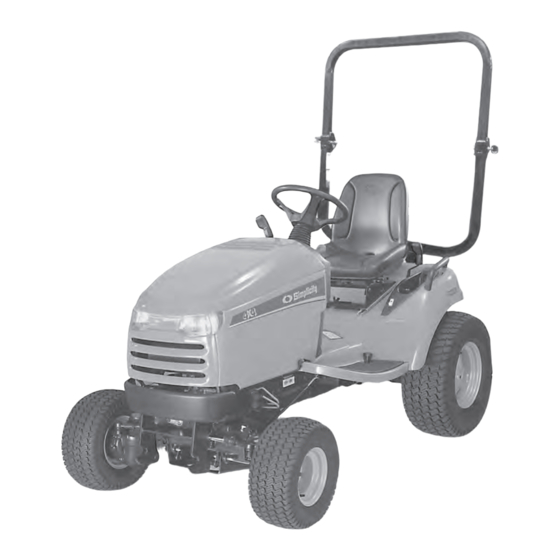
Operator's Manual
Model No.
2691312-00
2691313-00
2691314-00
1696105
1695058
Description
Legacy XL, 27HP, 2 WD
Legacy XL, 27HP, 4 WD
Legacy XL, 27HP, 4 WD
61" Mower Deck
54" Mower Deck
80012907USCN
Revision -
Advertisement

Related Manuals for Briggs & Stratton Legacy XL


Summary of Contents for Briggs & Stratton Legacy XL
- Page 1 Operator's Manual Model No. Description 2691312-00 Legacy XL, 27HP, 2 WD 2691313-00 Legacy XL, 27HP, 4 WD 2691314-00 Legacy XL, 27HP, 4 WD 1696105 61" Mower Deck 1695058 54" Mower Deck Copyright © 2014 Briggs & Stratton Power Products Group, LLC.
-
Page 3: Table Of Contents
CONTENTS Operator Safety ............... 4 Features and Controls ............12 Operation ................17 Safety Interlock System Tests ..........17 Mower Deck removal and Installaton ........27 Maintenance ................. 29 Troubleshooting, Adjustment and Service ......37 Specifications ................ 44 The images in this document are representative. Your unit may vary from the images displayed. LEFT and Right are see from the operator's position... -
Page 4: Operator Safety
Operator Safety Important Safety Instructions DANGER indicates a hazard which, if not SAVE THESE INSTRUCTIONS - This manual contains avoided, will result in death or serious injury. important instructions that should be followed during the initial set-up, the operation, and the maintenance of the WARNING indicates a hazard which, if not equipment. - Page 5 Operating Safety Congratulations on purchasing a superior-quality piece of lawn and garden equipment. Our products are designed and manufactured to meet or exceed all industry standards for safety. Power equipment is only as safe as the operator. If it is misused, or not properly maintained, it can be dangerous! Remember, you are responsible for your safety and that...
- Page 6 Slope Operation You could be seriously injured or even killed if you use this unit on too steep an incline. Using the unit on a slope that is too steep or where you don’t have adequate traction can cause you to lose control or roll over. A good rule of thumb is to not operate on any slope you cannot back up (in 2-wheel drive mode).
- Page 7 Read these safety rules and follow them closely. Failure to obey these rules could result in loss of control of unit, severe personal injury or death to you, or bystanders, or damage to property or equipment. This mowing deck is capable of amputating hands and feet and throwing objects. The triangle in text signifies important cautions or warnings which must be followed.
- Page 8 SLOPE OPERATION WARNING Slopes are a major factor related to loss-of-control and tip- Never operate on slopes greater than 17.6 percent (10°) over accidents, which can result in severe injury or death. which is a rise of 3-1/2 feet (106 cm) vertically in 20 feet Operation on all slopes requires extra caution.
- Page 9 SERVICE AND MAINTENANCE 12. Do not use gasoline containing METHANOL, gasohol containing more than 10% ETHANOL, gasoline additives, Safe Handling of Gasoline or white gas because engine/fuel system damage could result. 1. Extinguish all cigarettes, cigars, pipes, and other sources 13.
- Page 10 2. Make sure there isn’t any missing, damaged, or loose Roll Bar Instructions mounting hardware. WARNING 3. Make sure the ROLL BAR has been correctly and In order to avoid serious injury or death from roll over, it completely installed. is important to follow the warnings listed below.
- Page 11 Decal Locations (Safety and Operation) Throttle Speed, Ignition Switch, Part No. 1725571 Part No. 1722806 DANGER: Slopes, Blades, Tunnel Cover Part No. 1755389 1725571 DANGER: Do Not Operate W/O Deflector Lift Attachment, Part No. 7101665 Part No. 1725603 DANGER Amputation and thrown objects hazard Keep hands and feet away from deck.
-
Page 12: Features And Controls
Features and Controls Figure 2... - Page 13 Throttle Control Cutting Height Adjustment This controls the engine speed. Move the throttle The cutting height adjustment switch controls control to the FAST position to increase engine the mower cutting height. This same switch speed and SLOW position to decrease engine also controls the spout rotator motor when a speed.
- Page 14 Steering Tilt Adjust (Select Models) Power Outlet (Select Models) Use the tilt knob located on the bellows to The power outlet is 12V-DC. Accessory must be release the pivot mechanism and pivot the wheel rated at 14 amps or less. to the desired position.
- Page 15 Dashboard Display Functions Models with Liquid Cooled Engines See Figure 3. The dashboard display shows a variety of engine operation and control status information, as explained in the descriptions below. A. Irregular Voltage (Liquid Cooled Models) Indicates that the voltage being produced by the charging system and battery is higher or lower than normal levels.
- Page 16 Parking Brake Function Applying the Parking Brake - See Figure 4. To lock the parking brake, release the ground speed pedals (A), fully depress the brake pedal (B), pull the parking brake knob (C) out, and then release brake pedal. Releasing the Parking Brake - See Figure 4.
-
Page 17: Operation
Operation General Operating Safety Adding Fuel Be sure to read all information in the Operator Safety WARNING section before attempting to operate this unit. Become Fuel and its vapors are extremely flammable and familiar with all of the controls and how to stop the unit. explosive. - Page 18 Starting the Engine Stopping the Tractor and Engine 1. Return the ground speed control(s) to neutral and engage the parking brake. WARNING Fuel and its vapors are extremely flammable and 2. Disengage the PTO and wait for all moving parts to stop. explosive.
- Page 19 Reverse Mowing Option (RMO) Pushing the Tractor by Hand WARNING WARNING The engine will shut off if the reverse ground speed Towing the unit will cause transmission damage. Do not pedal is depressed while the PTO is on and the RMO use another vehicle to push or pull this unit.
- Page 20 Hydraulic System Function Raise and Lower the Roll Bar General WARNING Avoid serious injury or death from roll over: All of the inboard and auxiliary hydraulics are controlled by the attachment lift control lever. The attachment lift control lever raises and lowers attachments that utilize the tractor’s hydraulic lift cylinder.
- Page 21 Using Inboard Hydraulics Using Auxiliary Hydraulics The inboard hydraulics control the tractor’s belly attachment The attachment lift control is also used to control lift (mower deck) and three point hitch lift (if equipped). The attachments that use the tractor’s auxiliary hydraulic front / rear hydraulic selector switch must be in the REAR couplers located on the right and left front frame rails.
- Page 22 Pulling the lever back raises the attachment lift (A, Figure Optional 3-Point Hitch Operation 11). Pushing the lever forward to the first detent lowers the attachment lift (B). Pushing the lever forward to the second WARNING detent locks the control in “float” position, allowing the lift mechanism to float up and down.
- Page 23 Locking The Hitch Hitch Arms Installation The 3-point hitch can be locked in the raised position. 1. Attach the upper lift link (A, Figure 15) to the hitch When a rear attachment is locked in the raised position, the assembly (B)using a clevis pin (C) and safety clip (D). tractor’s on-board hydraulic cylinder can be used to lift mid 2.
- Page 24 5. Attach the adjustable link assembly (M, Figure 17) and Starting & Stopping the PTO lift link assembly (N) to sway arms (E) using clevis pins 1. Stop the engine and remove the key. Set the parking (O) and hair pin clips (P). brake.
- Page 25 Attaching a Trailer 540 Attachment Recommendations The maximum weight of a towed trailer should be less than GENERAL 800 lbs (363 kg). Secure the trailer with an appropriately This rear PTO was designed and tested with the 540 RPM sized clevis pin (A, Figure 20) and clip (B). rear tiller sold by Simplicity Manufacturing.
- Page 26 Storage 12 Volt Power Outlet (Select Models) WARNING WARNING Avoid Injury. Safe operation requires your full attention. Never store the unit (with fuel) in an enclosed, Do not wear radio or music headphones while operating unventilated structure. Fuel vapors can travel to an machine.
-
Page 27: Mower Deck Removal And Installaton
Mower Deck Removal & Installation 11. 61” mowers: Remove the two hair pin clips (C, Figure NOTE: Perform mower removal and installation on a hard, 23) from the spring assists (D), then unhook the two level surface such as a concrete floor. roller pivot springs (E) from the spring assists. - Page 28 15. Disconnect the electrical connection from the tractor and Installing the Mower Deck recap the tractor electrical socket. See Figure 25. 1. Slide the mower under the tractor. 2. Hook up the electrical connection (Figure 25). 3. Start the engine. 4.
-
Page 29: Maintenance
Maintenance Maintenance ENGINE Maintenance Chart First 5 Hours Change engine oil TRACTOR AND MOWER Every 8 Hours or Daily Every 8 Hours or Daily Check engine oil level Check safety interlock system Every 25 Hours or Annually * Clean debris off tractor and mower deck Clean engine air filter and pre-cleaner ** Clean debris from engine compartment Every 50 Hours or Annually *... - Page 30 Engine Maintenance - General 2. Liquid cooled models also have a removable radiator screen (B, Figure 29 & 30). Refer to the engine owner’s manual for all engine 3. To access the removable radiator screen (B, Figure maintenance procedures and recommendations. 30) on Kawasaki models, remove the hair pin clips (C) Clean Debris Out of Engine Compartment securing the transmission oil cooler (D).
- Page 31 Check Engine Coolant Level Change Engine Coolant Liquid Cool Models Only Liquid Cool Models Only Service Interval: Every 25 Hours, or As Necessary See Engine Manual for antifreeze recommendations and change intervals. See Figures 29 & 30 for drain plug (G) The engine coolant level and quality should be checked locations.
- Page 32 Check Transmission Oil Level Change Transmission Oil and Filter WARNING WARNING Do not allow dirt, water, or other debris to enter the Do not allow dirt, water, or other debris to enter the expansion chamber or transmission. Even a small expansion chamber or transmission.
- Page 33 Check Front Axle Oil Level (4 WD Models Check Mower Deck Gear Box Oil Only) Service Interval: Every Fall & Spring Service Interval: Every 25 Hours To check the mower deck gear box oil: Oil Type: 80W-90 Gear Lube 1. Place a shop towel under the side opening to keep oil off the belt and pulleys.
- Page 34 Cleaning the Battery and Cables Check Tire Pressure 1. Disconnect the cables from the battery, negative cable Tire pressure should be checked periodically, and first (A, Figure 36). maintained at the levels shown in the chart. Note that these pressures may differ slightly from the “Max Inflation” 2.
- Page 35 Lubrication Lubricate the unit at the locations shown in Figures 37-43 as well as the lubrication points listed. Generally, all moving metal parts should be oiled where contact is made with other parts. Keep oil and grease off belts and pulleys. Wipe surfaces clean before and after lubrication.
- Page 36 Grease the Electric Lift Rod Grease Fitting Yearly Grease the Deck Belt Idler Pulley Arm Grease Fitting Yearly Figure 41 Every 10 Hours Figure 42 Figure 43 LG/SS Mower Drive Shaft.epsf...
-
Page 37: Troubleshooting, Adjustment And Service
Troubleshooting, Adjustment and Service 5. Balance the blade as shown in Figure 45. Center the Servicing the Mower Blades blade’s hole on a nail lubricated with a drop of oil. A balanced blade will remain level. WARNING For your personal safety, do not handle the sharp mower blades with bare hands. - Page 38 Mower Adjustments Gauge Wheel Adjustment (54” Mower Only) The mower gauge wheels can be placed in two positions WARNING depending on the height of cut. When using higher cutting Before checking mower, shut off PTO and engine. Allow heights, set the wheels in the lower position. When using all moving parts to stop.
- Page 39 FRONT TO BACK LEVELING Mower Adjustments 1. Arrange the blades so they face front-to-back. 2. Measure the distance from the ground to the front of WARNING the front blade and from the rear tips of the rear blades. Before checking mower, shut off PTO and engine. Allow Front tips should be 1/8”...
- Page 40 7. Install the new drive belt as shown in the diagram in 54” & 61” Mower Drive Belt Replacement Figure 52. 1. Remove the mower deck. See Mower Removal 8. Reinstall the belt covers. Be sure the alignment notches and Installation are centered on the screws.
- Page 41 Headlight Replacement Seat Adjustment Seat Slide Adjustment 1. Open the hood. 2. Remove the forward heat shield. The seat can be adjusted forward and back. Move the lever (A, Figure 53), position the seat as desired, and release the 3. Remove the light bulb socket (A, Figure 55) from the lever to lock the seat into position.
- Page 42 Troubleshooting WARNING While normal care and regular maintenance will extend To avoid serious injury, perform maintenance on the the life of your equipment, prolonged or constant use may tractor or mower only when the engine is stopped and eventually require that service be performed to allow it to the parking brake engaged.
- Page 43 Troubleshooting the Mower PROBLEM CAUSE REMEDY Mower will not raise. 1. Lift linkage not properly attached or damaged Attach or repair. 2. Dirt in hydraulic lines. Change hydraulic system filter. Mower cut is uneven. 1. Mower not leveled properly. See Mower Adjustment. 2.
-
Page 44: Specifications
Specifications ENGINE Model KOHLER Command Horizontal Displacement 44 cu in. (725 cc) Electrical System Alternator: 20 Amp Regulated Battery: 12 Volt, 500 CCA Oil Capacity 2,1 qt. (2,0 L) Model KAWASAKI Liquid Cooled Displacement 45,50 cu in. (745 cc) Electrical System Alternator: 20 Amp Regulated Battery: 12 Volt, 500 CCA Oil Capacity...
Need help?
Do you have a question about the Legacy XL and is the answer not in the manual?
Questions and answers