Table of Contents
Advertisement
Quick Links
Modbus Protocol Reference Guide
1. INTRODUCTION ...................................................................................2
2. MODBUS PROTOCOL ..........................................................................3
2.1
GENERAL DESCRIPTIONS ..............................................................................................3
2.2
TRANSMISSION SETTING ................................................................................................3
2.3
SYSTEM CONFIGURATION EXAMPLES ..........................................................................4
2.4
MODBUS MESSAGE FRAMING ........................................................................................6
2.4.1 READ HOLDING REGISTERS ...............................................................................6
2.4.2 WRITE MULTIPLE REGISTERS .............................................................................7
2.4.3 CRC CALCULATION ALGORITHM .........................................................................8
3. MODBUS REGISTERS .........................................................................9
3.1
DEVICE INFORMATION ....................................................................................................9
3.2
I/O DATA ........................................................................................................................... 10
3.3
DEVICE CONTROL .......................................................................................................... 11
3.4
LOCKOUT SETTING ........................................................................................................ 11
3.5
INPUT SETTING .............................................................................................................. 12
3.5.1 COMMON SETTING ............................................................................................. 12
3.5.2 FORCED ZERO, TARE ADJUSTMENT V M AC ................................................. 12
3.5.3 DC VOLTAGE/CURRENT INPUT V .................................................................... 13
3.5.4 POTENTIOMETER INPUT M ............................................................................. 13
3.5.5 RTD INPUT R ..................................................................................................... 14
3.5.6 THERMOCOUPLE INPUT T ............................................................................... 14
3.5.7 AC VOLTAGE/CURRENT INPUT V .................................................................... 15
3.6
BARGRAPH SETTING ..................................................................................................... 16
3.7
ANALOG OUTPUT SETTING .......................................................................................... 16
3.8
ALARM SETTING ............................................................................................................. 17
3.8.1 COMMON SETTING ............................................................................................. 17
3.8.2 SETPOINTS & BANK SWITCHING ...................................................................... 18
3.8.3 ALARM TRIP ACTION........................................................................................... 19
3.9
OPERATION CONTROL SETTING .................................................................................. 19
3.10 DISPLAY SETTING ..........................................................................................................20
3.11 MODBUS SETTING .........................................................................................................20
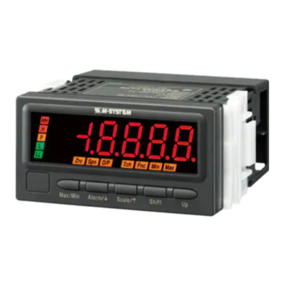
47D Series Digital Panel Meters
C O NTE NT S
47D Series Modbus Reference Guide EM-9501-C Rev.4
1
Advertisement
Table of Contents

Related Manuals for M-system 47D Series


Summary of Contents for M-system 47D Series
-
Page 1: Table Of Contents
ALARM SETTING ......................17 3.8.1 COMMON SETTING ..................... 17 3.8.2 SETPOINTS & BANK SWITCHING ..............18 3.8.3 ALARM TRIP ACTION................... 19 OPERATION CONTROL SETTING .................. 19 3.10 DISPLAY SETTING ......................20 3.11 MODBUS SETTING ......................20 47D Series Modbus Reference Guide EM-9501-C Rev.4... -
Page 2: Introduction
This Reference Guide explains the 47D series specifications regarding Modbus protocol. In this manual, descriptions given with the following symbols are applied only to the models those symbols are as- signed to. Other descriptions with no specific symbol are applied to all 47D Series models. Model No. -
Page 3: Modbus Protocol
MODBUS PROTOCOL GENERAL DESCRIPTIONS The 47D Series Digital Panel Meter (referred hereunder as ‘the device’) is applicable with Modbus RTU mode. ASCII mode is not usable. Detailed information about Modbus Protocol is described in MODBUS APPLICATION PROTOCOL V1.1a / Modbus over Serial Line Specification &... -
Page 4: System Configuration Examples
Identical setting for all devices connected via the RS-232C/RS-485 Converter. Parity bit Identical setting for all devices connected via the RS-232C/RS-485 Converter. Stop bit Identical setting for all devices connected via the RS-232C/RS-485 Converter. 47D Series Modbus Reference Guide EM-9501-C Rev.4... - Page 5 Analog output and Modbus functions are stopped while in this mode. Note 2: The COP-IRU can communicate with single panel meter only. DO NOT turn more than one panel meter on to the infrared communication mode. 47D Series Modbus Reference Guide EM-9501-C Rev.4...
-
Page 6: Modbus Message Framing
Here is an example of a response to read ‘0009’ at the register 3, ‘0000’ at the register 4. The register 3 ranges for two words, thus the register value shows ‘00000009.’ 01 03 04 00090000 2A31 (1) (2) (3) The above examples are given in hexadecimal. 47D Series Modbus Reference Guide EM-9501-C Rev.4... -
Page 7: Write Multiple Registers
Here is an example of a request to write ‘6600’ (000019C8) at the 2-word register 5604 (15E3) in the device address 01 10 15E3 0002 04 19C80000 C9C0 (1) (2) ■ RESPONSE EXAMPLE 01 10 15E3 0002 B432 (1) (2) The above examples are given in hexadecimal. 47D Series Modbus Reference Guide EM-9501-C Rev.4... -
Page 8: Crc Calculation Algorithm
CRC16 = (CRC16 And &HFF00) Or ((CRC16 And 255) Xor Message(I)) For N = 1 To 8 CarryBit = CRC16 And 1 CRC16 = ((CRC16 And &HFFFE) \ 2) And &H7FFF If CarryBit Then CRC16 = &HA001 Xor CRC16 Next Next End Function 47D Series Modbus Reference Guide EM-9501-C Rev.4... -
Page 9: Modbus Registers
26th character 25th character 28th character 27th character 30th character 29th character 32th character 31th character 9630 Reserved 9632 Tag name Unicode. Each character is assigned to 1 word. Master can write this register. 47D Series Modbus Reference Guide EM-9501-C Rev.4... -
Page 10: I/O Data
*2. Display value, Max value, Min value and Analog output are indefinite during the infrared communication mode. *3. Analog output is valid only when the device status code for the analog output equals ‘1.’ It is indefinite when the code equals ‘0.’ 47D Series Modbus Reference Guide EM-9501-C Rev.4... -
Page 11: Device Control
1 : Unlock Forzed Zero control / Lock Tare Adjustment control 2 : Lock Forced Zero and Tare Adjustment control Loop test output lockout 0 : Unlock Loop Test Output mode (*) 1 : Lock Loop Test Output Mode (*): Factory setting 47D Series Modbus Reference Guide EM-9501-C Rev.4... -
Page 12: Input Setting
0 : Disable Forced zero (*) 1 : Enable Forced zero 2 : Enable Tare adjustment 1022 Force zero value Set value : -20000 ... 100000 1024 Tare adjustment value Set value : -20000 ... 100000 47D Series Modbus Reference Guide EM-9501-C Rev.4... -
Page 13: Dc Voltage/Current Input V
Display decimal point position Applied to the scaling values and other values set in the scaled range. 0 : 00000 1 : 0000.0 2 : 000.00 (*) 3 : 00.000 4 : 0.0000 47D Series Modbus Reference Guide EM-9501-C Rev.4... -
Page 14: Rtd Input R
Factory setting : 0 °F/100 1071 Input compensation B compensation value °C/100 -99999 ... 999999 Factory setting : 0 °F/100 *5. Input compensation is not executed when the A and B values are equal. 47D Series Modbus Reference Guide EM-9501-C Rev.4... -
Page 15: Ac Voltage/Current Input V
Applied to the scaling values and other values set in the scaled range. 0 : 00000 1 : 0000.0 2 : 000.00 3 : 00.000 4 : 0.0000 Factory setting : VV 0.0000 / VA 00.000 47D Series Modbus Reference Guide EM-9501-C Rev.4... -
Page 16: Bargraph Setting
0% adjustment value ≤ 100% adjustment value – 5000 Factory setting : 0 3009 Analog output 100% adjustment %/1000 0 ... 105000 0% adjustment value + 5000 ≤ 100% adjustment value Factory setting : 100000 47D Series Modbus Reference Guide EM-9501-C Rev.4... -
Page 17: Alarm Setting
With ‘2,’ Bank No. specified at Register 801 is used. In actual applications, use Register 801 to switch Bank No. via Modbus communication by setting this register to ‘2.’ Register 4101 is not suitable for frequent switching during operation. 47D Series Modbus Reference Guide EM-9501-C Rev.4... -
Page 18: Setpoints & Bank Switching
Identical to Bank 1 setting (4102 ... 4112) 4173 4174 Bank 7 setpoints Identical to Bank 1 setting (4102 ... 4112) 4185 4186 Bank 8 setpoints Identical to Bank 1 setting (4102 ... 4112) 4197 47D Series Modbus Reference Guide EM-9501-C Rev.4... -
Page 19: Alarm Trip Action
Transition time to the lockout control mode The displays can be switched to Lockout Control Mode when the designated buttons are held down for a preset time period. 0 ... 99 : Seconds Factory setting : 5 47D Series Modbus Reference Guide EM-9501-C Rev.4... -
Page 20: Display Setting
T3.5 timer 1 ... 60 (character length x10) Factory setting : 35 7007 Long register 0 : Normal, Low-digit word at the lower address (*) 1 : Swap, High-digit word at the lower address 47D Series Modbus Reference Guide EM-9501-C Rev.4... - Page 21 M-System, or from M-System’s authorized distributors or resel- Period, the purchaser must promptly (and, in any event not lers, for its own use not for resale, that the M-System products more than 30 days after the discovery of such failure) notify...
Need help?
Do you have a question about the 47D Series and is the answer not in the manual?
Questions and answers